
Construction of 3D printing device for producing components

A kind of equipment, 3D technology, applied in the direction of 3D object support structure, processing and manufacturing, manufacturing tools, etc., can solve problems such as damaged construction area, unusable molded parts, damaged molded parts, etc., to achieve high-quality results

Active Publication Date:
View PDF6 Cites 6 Cited by
  • Summary
  • Abstract
  • Description
  • Claims
  • Application Information

AI Technical Summary

Problems solved by technology

They can damage the build area and thus the molded part to be manufactured, and even render the manufactured molded part unusable

Method used


Image

  • Construction of 3D printing device for producing components
  • Construction of 3D printing device for producing components
  • Construction of 3D printing device for producing components

Examples


Embodiment Construction

[0069] Preferred embodiments are shown in the accompanying drawings:

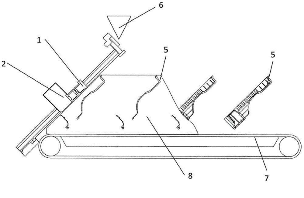
[0070] figure 1 The functional principle of the continuous 3D printing process is shown. The left side shows the front side of the machine, including the build area on which components are manufactured layer by layer. Coating of the individual layers is carried out at angles smaller than the specific angle of repose of the particulate material being treated. The conveyor belt (7) moves the feed material (8) to the right to the rear side of the machine. Finished parts can be removed here.

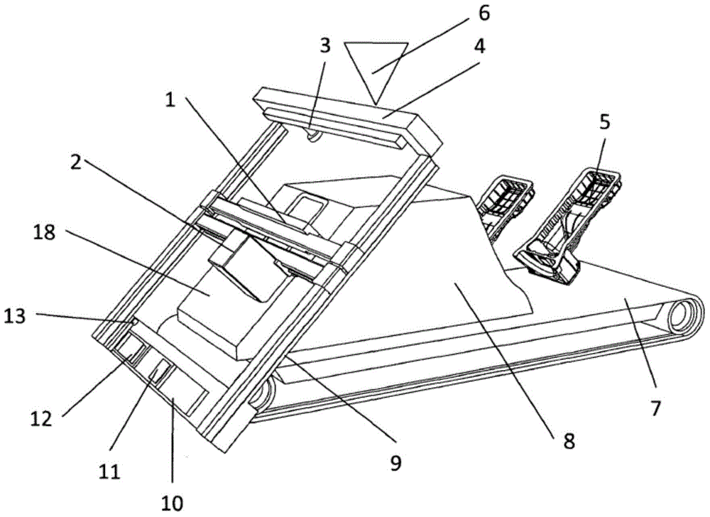
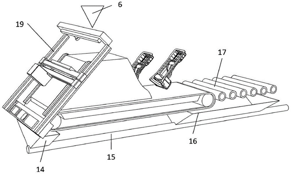
[0071] figure 2 A preferred structure of the invention is shown. Axis systems (9) for positioning the print heads are arranged on the left and right of the build area (18) on the front side of the machine. The applicator filling unit (4) and applicator cleaning unit (3) are located on top behind the build area. Excess particulate material from cleaning or filling operations of the applicator falls on the feed wit...


PUM


Abstract

The invention relates to a device for producing three-dimensional models, comprising a coater (1) with an ejection opening and at least one printing head (2) which is mounted on a printing shaft, wherein the ejection opening of the coater is arranged towards the top in the coating direction and the printing head (2) is arranged counter to the coating direction with the opposite orientation on the printing shaft behind the coater (1) in the coating direction. The invention further relates to a method for producing three-dimensional models.

Description

technical field [0001] The present invention relates to a device and a method for constructing a 3D (three-dimensional) model layer by layer. Background technique [0002] European Patent Specification EP 0 431 924 B1 describes a method for producing 3D models from computer data. A first material, here a granular material, is applied in a thin layer to the build platform, which may be surrounded by a container if desired, and then a second material, which may form a solid with the first material, is applied thereon. According to EP 0 431 924 B1, for example a granular material is provided as a first material and then a binder material is selectively printed onto the granular material using a printing head. The areas of the particles on which the binder has been printed bond together and harden under the influence of the binder and, if necessary, the addition of a curing agent. The platform is then lowered towards the build cylinder a distance of one layer thickness and pro...

Claims


Application Information

Patent Timeline
Patent Type & Authority Applications(China)
IPC IPC(8): B29C67/00
CPCB29C67/0081B29C67/0077B29C64/153B29C64/165B29C64/35B29C64/357B29C64/141B33Y10/00B33Y30/00Y02P10/25B22F10/14B22F10/73B22F12/55B33Y40/00B28B1/001B29K2105/251
Inventor 英戈·埃德雷尔安德烈斯·多米尼克·哈特曼多米尼克·施密德
Learn More