Low-voltage high-current-beam electron beam vacuum welding device and method

A vacuum welding and low voltage technology, applied in the direction of electron beam welding equipment, welding equipment, manufacturing tools, etc., can solve the problems of complicated preparation and high operating cost, and achieve the effect of long service life, low working environment requirements and high insulation strength

Inactive Publication Date: 2015-08-12
HARBIN INST OF TECH
View PDF10 Cites 16 Cited by
  • Summary
  • Abstract
  • Description
  • Claims
  • Application Information

AI Technical Summary

Problems solved by technology

[0006] In order to solve the problems of complex preparations before electron beam welding and high operating costs, the present invention further proposes a low-voltage, high-beam current electron beam vacuum welding device and method

Method used


Image

  • Low-voltage high-current-beam electron beam vacuum welding device and method

Examples


specific Embodiment approach 1

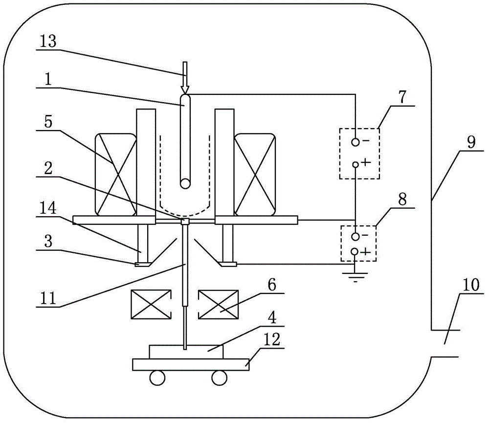
[0017] Specific implementation mode one: combine figure 1 Describe this embodiment, a low-voltage, high-current electron beam vacuum welding described in this embodiment includes a hollow cathode 1, an anode 2, an accelerating electrode 3, an axial confining magnetic field 5, a focusing mechanism 6, a discharge power source 7, and an accelerating power source 8 , a vacuum chamber 9, a welding platform 12 and an insulating sleeve 14, an axial confinement magnetic field 5, an insulating sleeve 14, an accelerating electrode 3, a focusing mechanism 6, and a welding platform 12 are sequentially arranged in the vacuum chamber 9 from top to bottom, and a hollow cathode 1 is inserted Installed in the axial confinement magnetic field 5, the anode 2 is set between the hollow cathode 1 and the accelerating electrode 3, and the anode 2 is located directly below the hollow cathode 1, the workpiece 4 is placed on the working platform 12, the negative pole of the discharge power supply 7 is c...

specific Embodiment approach 2

[0018] Specific implementation mode two: combination figure 1 To illustrate this embodiment, the low-voltage, high-current electron beam vacuum welding described in this embodiment further includes a pumping mechanism 10 , which is connected to the gas outlet of the vacuum chamber 9 . Other components and connections are the same as those in the first embodiment.

specific Embodiment approach 3

[0019] Specific implementation mode three: combination figure 1 To illustrate this embodiment, the hollow cathode 1 of a low-voltage, high-current electron beam vacuum welding device described in this embodiment is made of a tantalum tube or a molybdenum tube. Other components and connections are the same as those in the first embodiment.


PUM

PropertyMeasurementUnit
diameteraaaaaaaaaa

Abstract

The invention relates to a vacuum welding device and method, in particular to a low-voltage high-current-beam electron beam vacuum welding device and method. The low-voltage high-current-beam electron beam vacuum welding device and method are used for solving the problems that in the prior art, preparation before electron beam welding is complex and the operating cost is high. The low-voltage high-current-beam electron beam vacuum welding device comprises a hollow cathode, an anode, an accelerating electrode, an axial constraint magnetic field, a focusing mechanism, a discharging power supply, an accelerating power supply, a vacuum chamber, a welding platform and an insulating sleeve, wherein the axial constraint magnetic field, the insulating sleeve, the accelerating electrode, the focusing mechanism and the welding platform are arranged in the vacuum chamber in sequence from top to bottom, the hollow cathode is inserted into the axial constraint magnetic field, the anode is arranged between the hollow cathode and the accelerating electrode and located under the hollow cathode, a workpiece is placed on the working platform, the negative electrode of the discharging power supply is connected with the hollow cathode, the positive electrode of the discharging power supply and the negative electrode of the accelerating power supply are connected with the anode, and the accelerating power supply is connected with the accelerating electrode. The low-voltage high-current-beam electron beam vacuum welding device and method are used in the welding field.

Description

technical field [0001] The invention relates to a vacuum welding device and method, in particular to a low voltage and high beam current electron beam vacuum welding device and method, belonging to the field of welding. Background technique [0002] The vacuum environment is considered to be an ideal way to protect the molten pool due to the extremely low content of harmful gases. Wu Lin, Feng Jicai, Gao Hongming, et al. Space welding technology [J]. Aviation Manufacturing Technology, 2005, 5:32-35. It is believed that with the rapid development of international space research, there is a constant demand for space station repair and welding material connection technology Therefore, it is of great significance for the research of fusion welding method in vacuum environment. Currently, widely used welding methods in a vacuum protection environment mainly include: Hollow Cathode Vacuum Arc (HCVA) welding, electron beam welding and laser welding, and different welding methods h...

Claims


Application Information

Patent Timeline
Patent Type & Authority Applications(China)
IPC IPC(8): B23K15/06B23K15/02B23K103/04B23K103/10
CPCB23K15/02B23K15/0046B23K15/06B23K2103/04B23K2103/10
Inventor 田修波许建平巩春志
Owner HARBIN INST OF TECH
Why Eureka
Try Eureka