Cross-shaped sliding block third axis group mechanism of Swiss-type turning-milling machine tool

A cross-slide and shaft group technology, applied in metal processing mechanical parts, metal processing, metal processing equipment and other directions, can solve the problems of inability to realize complex parts, and achieve the effect of avoiding resistance, improving self-precision, and reducing heat generation.

Inactive Publication Date: 2015-08-12
NANJING JIANKE MACHINERY
View PDF6 Cites 2 Cited by
  • Summary
  • Abstract
  • Description
  • Claims
  • Application Information

AI Technical Summary

Problems solved by technology

[0005] The technical problem solved by the invention is the problem that the existing rotary milling machine tool cannot realize the one-time processing and forming of complex parts, and the efficiency is not high

Method used


Image

  • Cross-shaped sliding block third axis group mechanism of Swiss-type turning-milling machine tool
  • Cross-shaped sliding block third axis group mechanism of Swiss-type turning-milling machine tool
  • Cross-shaped sliding block third axis group mechanism of Swiss-type turning-milling machine tool

Examples


Embodiment 1

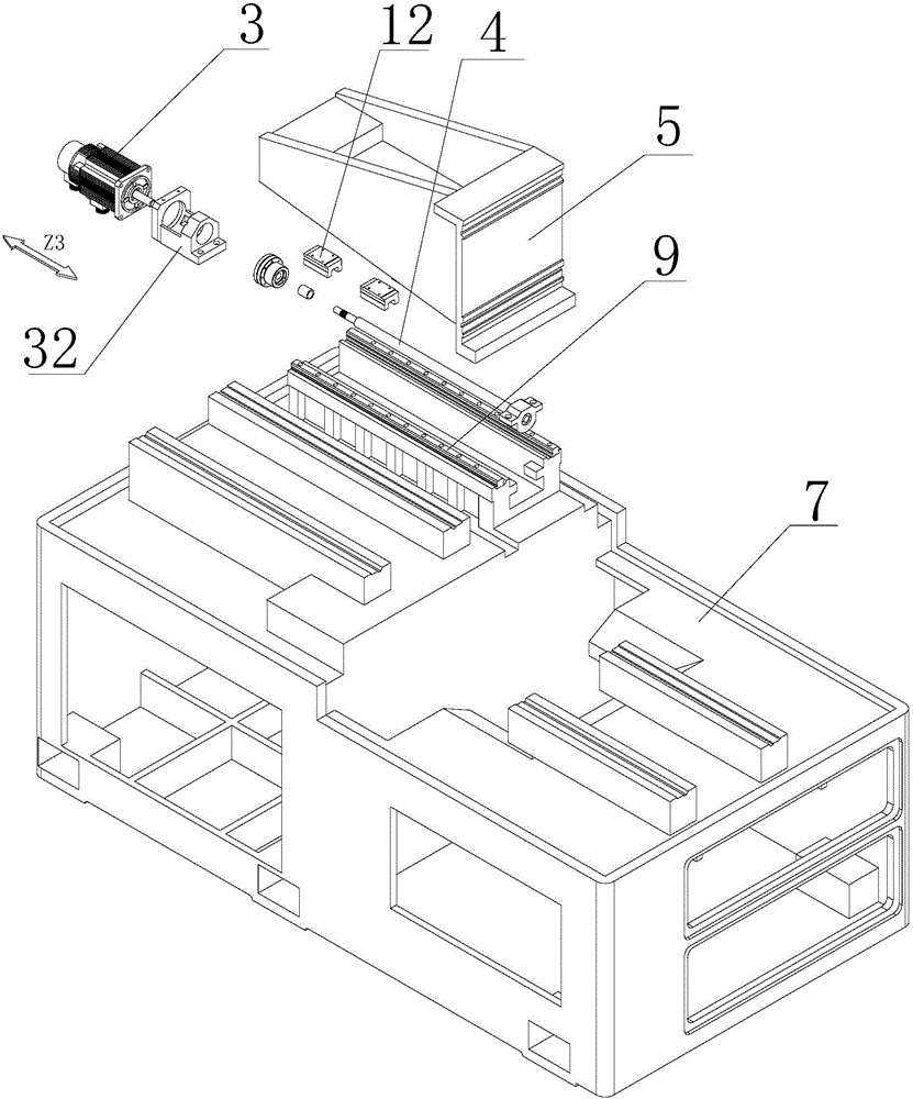
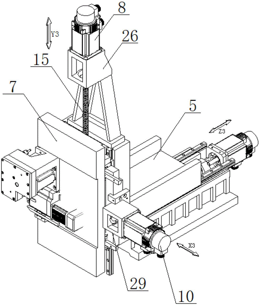
[0049] like Figure 1 to Figure 3 The mechanism of the third axis group of the cross slide on the center-type turning and milling machine shown includes the bed 1; the Z3 axis group, the X3 axis group and the Y3 axis group arranged on the bed 1, and the Z3 axis group Including the Z3 axis motor 3, the Z3 axis screw rod 4, the Z3 axis slide plate 5, the Z3 axis coupling and the Z3 axis motor seat 32 arranged on the bed 1 for installing the Z3 axis motor 3, the Z3 axis motor 3 The Z3-axis slide plate 5 is driven to reciprocate on the bed 1 along the Z-axis direction by the Z3-axis screw 4. The Z3-axis slide plate 5 is slidably installed on the bed 1. The specific sliding is that the bed 1 is provided with a Z3 axis. Rail 9, the bottom of the Z3 axis slide plate 5 is provided with a Z3 axis slide block 12 matched with the Z3 axis rail 9, the bottom of the Z3 axis slide plate 5 is provided with a Z3 axis nut, and the Z3 axis screw rod 4 passes through the Z3 axis nut; The Z3 shaf...

Embodiment 2

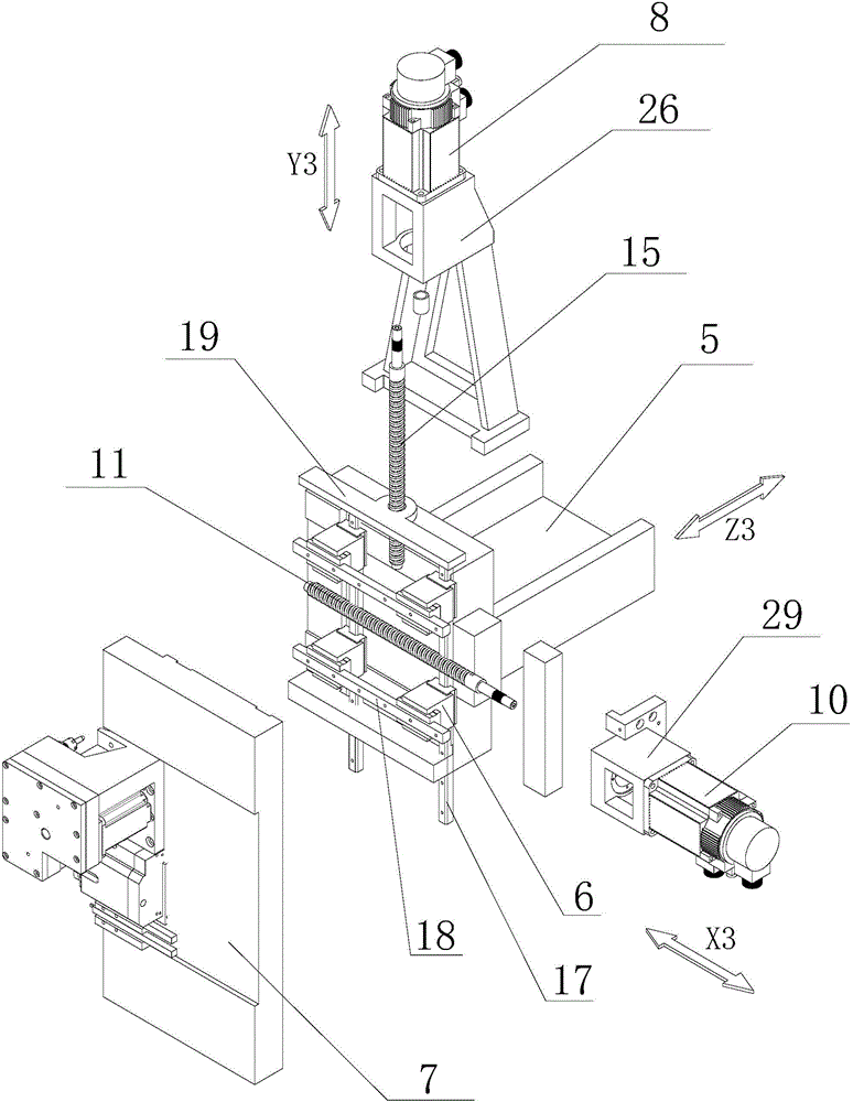
[0052] The difference between this embodiment and the structure of Embodiment 1 is that the tool mounting seat 7 is a turret, and the X3 axis rail 18 matched with the cross slider 6 is installed on the turret, so as to realize the movement of the turret in the X-axis direction. Tool, power head, etc. are installed on the turret, and the 360-degree rotation of the turret is used to realize tool change, saving time for tool change. The rest of the structure is the same as that of Embodiment 1, see Embodiment 1 for details, and will not be described in detail here. At this time, the turret rotates 360°, and the tools at each station of the turret can be changed flexibly to realize the processing of the workpiece. This assembly structure not only saves space, but also can be installed on the turret. Increase the variety and quantity of cutting tools, power heads, etc. to a certain extent, and the disc design is conducive to chip removal when the tool is processing parts, and to a ...

Embodiment 3

[0054]Compared with the first embodiment, the tool mounting seat 7 in this embodiment is composed of the X3-axis slide plate and the turret. The difference is that the turret is installed on the X3-axis slide plate, and the tool is installed on the turret. The 360-degree rotation of the turret can also be used. Realize tool change and save tool change time. The rest of the structure is the same as that of Embodiment 1, and will not be described in detail here. At this time, the turret rotates 360°, and the tools at each station of the turret can be changed flexibly to realize the processing of the workpiece. This assembly structure not only saves space, but also can be installed on the turret. Increase the variety and quantity of cutting tools, power heads, etc. to a certain extent, and the disc design is conducive to chip removal when the tool is processing parts, and to a greater extent strengthens the rigidity of the tool when processing parts. Such a structure increases t...


PUM


Abstract

The invention discloses a cross-shaped sliding block third axis group mechanism of a Swiss-type turning-milling machine tool. The cross-shaped sliding block third axis group mechanism of the Swiss-type turning-milling machine tool comprises a Z3-axis group arranged on a machine tool bed, a Y3-axis group and an X3-axis group, wherein the Z3-axis group comprises a Z3-axis servo motor, a Z3-axis lead screw and a Z3-axis sliding plate, the Z3-axis sliding plate is installed on the machine tool bed, the Z3-axis lead screw is in threaded connection with the Z3-axis sliding plate, one end of the Z3-axis lead screw is connected with a transmission shaft of the Z3-axis servo motor, the Y3-axis group comprises cross-shaped sliding blocks which are arranged on the Z3-axis sliding plate in a sliding mode, a Y3-axis servo motor, a sliding seat and a Y3-axis lead screw, the Y3-axis lead screw is in threaded connection with the sliding seat, one end of the Y3-axis lead screw is connected with a transmission shaft of the Y3-axis servo motor, the X3-axis group comprises a cutter mounting base, an X3-axis servo motor and an X3-axis lead screw, the X3-axis lead screw is in threaded connection with the cutter mounting seat, and one end of the X3-axis lead screw is connected with a transmission shaft of the X3-axis servo motor. The cross-shaped sliding block third axis group mechanism of the Swiss-type turning-milling machine tool has the advantage of solving the problems that for an existing computer numerical control precision turning-milling machine tool, one-time machining forming of complex parts can not be achieved, and the machining efficiency is not high.

Description

technical field [0001] The invention relates to a third shaft group mechanism of a cross slider on a center turning type turning and milling machine tool. Background technique [0002] In the existing centering machine market, there has been research on the technology of machine tool motion axes, and the most widely used one is the three-axis with positive axis structure consisting of X1 axis group, Y1 axis group, and Z1 axis group. Swivel type turning and milling machine; or, when the sub-axis structure is added with Z2 axis group, it can be combined with the positive axis structure to form a four-axis swivel type turning and milling machine tool; or, when the sub-axis is composed of X2 axis group and Z2 axis group The sub-axis structure is combined with the positive axis structure to form a five-axis center-type turning and milling machine tool; or, when the sub-axis structure composed of X2 axis group, Z2 axis group, and Y2 axis group is combined with the positive axis st...

Claims


Application Information

Patent Timeline
Patent Type & Authority Applications(China)
IPC IPC(8): B23Q5/40B23Q37/00
CPCB23Q5/40B23Q37/00
Inventor 王建飞
Owner NANJING JIANKE MACHINERY
Why Eureka
Try Eureka