Manual hydraulic lifting device in machining

A technology of hydraulic lifting and machining, applied in the direction of lifting devices, etc., can solve the problems of complex equipment structure, small floor space and large floor space, and achieve the effect of solving the complex structure, small floor space and low cost of equipment.

Inactive Publication Date: 2015-08-12
CHENGDU DAMO PETROLEUM MACHINERY GRP
View PDF0 Cites 4 Cited by
  • Summary
  • Abstract
  • Description
  • Claims
  • Application Information

AI Technical Summary

Problems solved by technology

[0003] The purpose of the present invention is to overcome the problems of complex structure, large footprint and high use cost of the above-mentioned existing equipment for lifting the height of metal parts, and a manual hydraulic lifting device in mechanical processing is designed. The structure is simple, the principle is simple, and t

Method used


Image

  • Manual hydraulic lifting device in machining

Examples


Embodiment 1

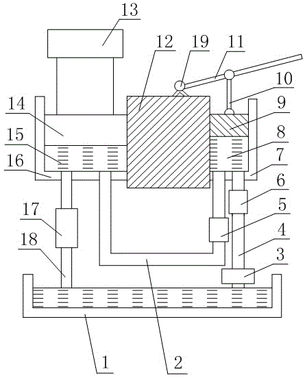
[0013] Such as figure 1 As shown, the manual hydraulic lifting device in mechanical processing includes an oil tank 1, a hydraulic pump 3 is arranged above the oil tank 1, the hydraulic pump 3 is connected to the oil tank 1, and a large hydraulic cylinder 16 communicating with each other is arranged above the hydraulic pump 3 and the small hydraulic cylinder 7, the large hydraulic cylinder 16 and the small hydraulic cylinder 7 are all connected with the oil tank 1, the small hydraulic cylinder 7 is connected with the hydraulic pump 3, and the tops of the large hydraulic cylinder 16 and the small hydraulic cylinder 7 are all provided with openings, the large hydraulic cylinder A positioning block 12 is arranged between the cylinder 16 and the small hydraulic cylinder 7, and the positioning block 12 is fixed with the large hydraulic cylinder 16 and the small hydraulic cylinder 7 at the same time. The inner wall of the hydraulic cylinder 16 is in seamless contact, and the large p...


PUM


Abstract

The invention discloses a manual hydraulic lifting device in machining. A hydraulic pump is arranged above an oil tank and is connected to the oil tank, wherein a large hydraulic cylinder and a small hydraulic cylinder are arranged above the hydraulic pump; the small hydraulic cylinder is connected to the hydraulic pump; an opening is formed in the top of each of the large hydraulic cylinder and the small hydraulic cylinder; a positioning block is arranged between the large hydraulic cylinder and the small hydraulic cylinder and is fixed to the large hydraulic cylinder and the small hydraulic cylinder; a large piston is arranged in the large hydraulic cylinder; a support table is fixed on the top of the large piston and is arranged above the large hydraulic cylinder; a small piston is arranged in the small hydraulic cylinder; a pressing rod is arranged above the positioning block; the pressing rod is connected to a connector; the connector is fixed to the positioning block; a connection rod is arranged under the pressing rod and is respectively connected to the pressing rod and the small piston. The manual hydraulic lifting device is simple in structure, simple in principle, small in occupied area, low in cost and convenient to carry; metal parts can be lifted by using the principles of levers and hydraulic pressure; the manual hydraulic lifting device can be conveniently operated by operators.

Description

technical field [0001] The invention relates to a device, in particular to a manual hydraulic lifting device in machining. Background technique [0002] Petroleum, also known as crude oil, is a viscous, dark brown liquid. There are oil reserves in parts of the upper crust. The main component is a mixture of various alkanes, naphthenes and aromatic hydrocarbons. It is formed by the long-term evolution of organisms in ancient oceans or lakes, and it belongs to fossil fuels. Petroleum is mainly used as fuel oil and gasoline, and is also a raw material for many chemical industry products such as solutions, fertilizers, pesticides and plastics. The nature of petroleum varies with the place of origin, the density is 0.8-1.0g / cm3, the viscosity range is very wide, the freezing point varies greatly (30-60 degrees Celsius), the boiling point ranges from room temperature to above 500 degrees Celsius, and is soluble in various organic solvents. Insoluble in water, but can form emul...

Claims


Application Information

Patent Timeline
IPC IPC(8): B66F3/24B66F3/26
CPCB66F3/42B66F3/24B66F3/26
Inventor 贺昶明
Owner CHENGDU DAMO PETROLEUM MACHINERY GRP
Why Eureka
Try Eureka