Electrical sheet plasma suspension device and manufacturing method thereof

A suspension device, plasma technology, applied in the direction of manufacturing tools, furnace types, furnaces, etc., can solve problems such as surface damage of annealed steel strips, achieve high grades, low magnetic properties, and reduce damage or nodules.

Active Publication Date: 2015-08-12
MAGANG (GROUP) HOLDING CO LTD +1
View PDF8 Cites 2 Cited by
  • Summary
  • Abstract
  • Description
  • Claims
  • Application Information

AI Technical Summary

Problems solved by technology

[0006] Since the annealing of high-silicon electrical steel needs to go through high humidity and high temperature environment, the surface of the steel is oxidized, and then reduced under high hydrogen atmosphere and high temperature conditio

Method used


Image

  • Electrical sheet plasma suspension device and manufacturing method thereof

Examples


Embodiment 1

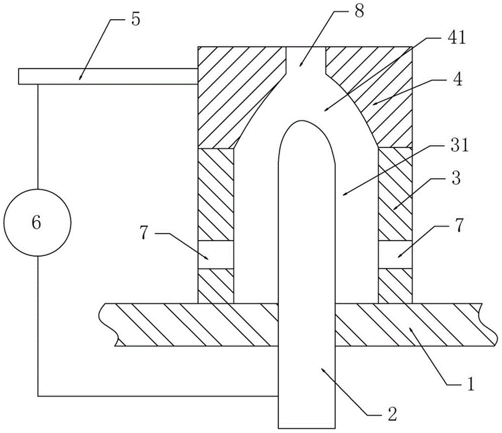
[0034] see figure 1 , an electrical steel plasma levitation device, comprising a support seat and an electrode rod 2;

[0035] The support seat is fixedly connected to the furnace floor 1 and insulated from the furnace floor 1, and a cavity is arranged in the support seat;

[0036] The electrode rod 2 extends into the cavity of the support seat;

[0037] The upper end surface of the support seat is provided with an outlet 8 for gas ejection in the cavity of the support seat, and the upper end surface of the support seat is a support surface of electrical steel; the lower end of the support seat is provided with an inlet 7 for gas to enter the cavity from the furnace;

[0038] The power supply 6 is connected to the electrode rod 2 and the support seat through a circuit, and the part of the support seat connected to the circuit is made of conductive material.

[0039] The support seat is formed by connecting the upper seat 4 and the lower seat 3, the upper seat 4 is heat-resis...

Embodiment 2

[0049] A method for manufacturing the above-mentioned electrical steel plasma suspension device, comprising the following steps:

[0050] 1) Make a hole in the furnace floor 1, and let the electrode rod 2 pass through the hole and extend into the furnace;

[0051] 2) The lower seat 3 with the inlet 7 is set on the electrode rod 2 and fixedly connected with the furnace floor 1;

[0052] 3) Connect the upper seat 4 with a hemispherical cavity inside to the lower seat 3, and the spherical end of the electrode rod 2 extends into the upper cavity 41 of the upper seat 4;

[0053] 4) Connect the conductive rod 5 on the upper seat 4, and the conductive rod 5 extends out of the furnace;

[0054] 5) The power supply 6 located outside the furnace connects the conductive rod 5 and the part of the electrode rod 2 located outside the furnace through a circuit.

[0055] figure 1The high-temperature plasma high-flow generating device shown. The high-temperature plasma high-flow generating...


PUM


Abstract

The invention discloses an electrical sheet plasma suspension device and a manufacturing method thereof. The electrical sheet plasma suspension device comprises a support seat and an electrode bar (2), wherein the support seat is fixedly connected with a furnace bottom plate (1) and is insulated from the furnace bottom plate (1); a cavity is arranged in the support seat; the electrode bar (2) extends into the cavity of the support seat; an outlet (8), through which gas in the cavity of the support seat is ejected, is formed in the upper end surface of the support seat; the upper end surface of the support seat is an electrical sheet supporting surface; an inlet (7), through which gas flows into the cavity from a furnace, is formed in the lower end of the support seat; a power supply (6) is connected with the electrode bar (2) and the support seat through a circuit; and the part, which is connected with the circuit, of the support seat is made of a conductive material; and the gas flowing into the cavity through the inlet (7) discharges electricity in an upper cavity (41) and a lower cavity (31) to form plasma, and then is ejected from the outlet (8) to a running steel strip to form a support for the steel strip so as to avoid or reduce the surface damage of the annealed steel strip.

Description

technical field [0001] The invention belongs to the technical field of electrical steel processing equipment, and in particular relates to an electrical steel plasma suspension device and a manufacturing method thereof. Background technique [0002] The large-scale continuous production of cold-rolled high-grade electrical steel is realized by increasing the Si and Al content of the steel, reducing the impurity elements of the steel, reasonable hot rolling and providing continuous annealing (high temperature). The higher the grade of high-grade electrical steel, the lower the iron loss. Iron loss reduction, cold rolling annealing temperature increase is an essential means. [0003] The annealing of cold-rolled non-oriented electrical steel is realized in a continuous annealing furnace. The function of the continuous annealing furnace can realize the removal of excess carbon from the steel and the high annealing temperature to achieve the required recrystallization under th...

Claims


Application Information

Patent Timeline
IPC IPC(8): C21D9/63C21D1/26
Inventor 王立涛裴陈新施立发裴英豪
Owner MAGANG (GROUP) HOLDING CO LTD
Why Eureka
Try Eureka