Feeding mechanism and biomass burner applying same
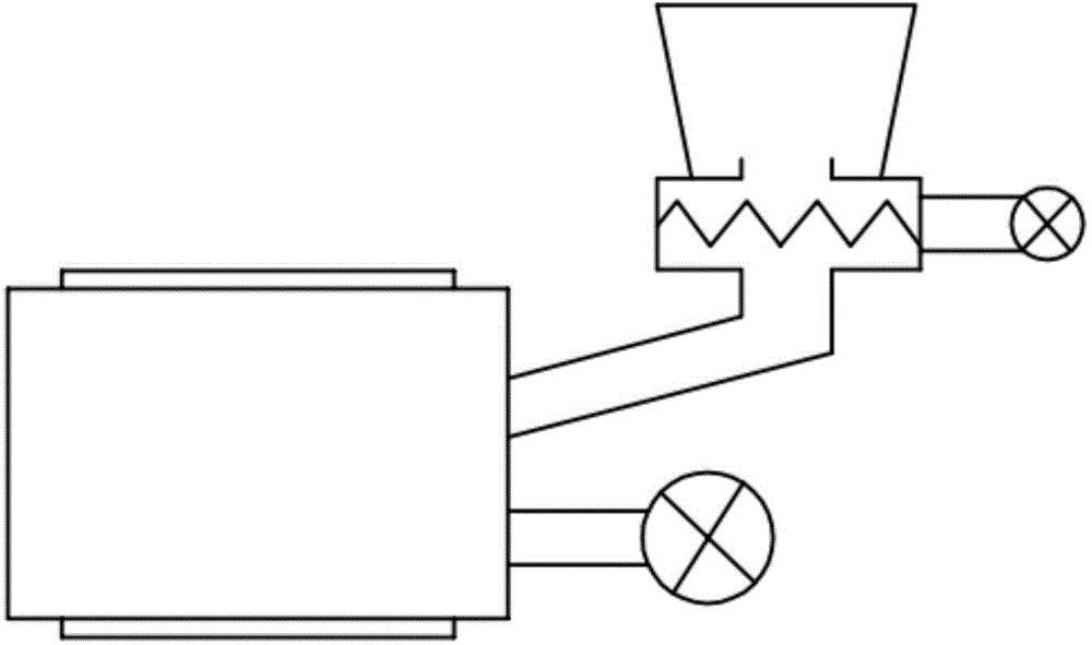
A technology of feeding mechanism and combustion chamber is applied in the field of biomass energy utilization, which can solve the problems of increasing the fluidity of biomass particles, and achieve the effects of simple structure, sufficient combustion, and avoiding accumulation and blockage.
- Summary
- Abstract
- Description
- Claims
- Application Information
AI Technical Summary
Problems solved by technology
Method used
Image
Examples
Embodiment 1
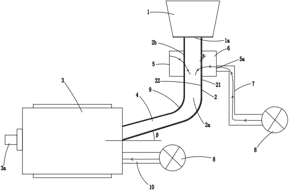
[0030] figure 2 It is a structural schematic diagram of Embodiment 1 of a feeding mechanism of the present invention; figure 2 As shown, a feeding mechanism includes a silo 1, the discharge port 1a of the silo 1 communicates with a feeding channel 2, and the channel outlet 2a provided at the bottom of the feeding channel 2 and one end can be communicated to the combustion chamber 3. The feed channel 4 is connected, and the feed channel 4 is arranged obliquely; the outside of the feed channel 2 is provided with a sleeve 5, and an airtight cavity 6 is formed between the inner wall of the sleeve 5 and the outer wall of the feed channel 2, and placed The side wall of the feed channel 2 in the cavity 6 is provided with a plurality of through holes 2b from the outer wall 21 to the inner wall 22, and the air inlet 5a of the sleeve 5 is connected to an air duct 7, and the end of the air duct 7 is provided with A blower 8, the gas is introduced into the cavity 6 through the blower 8...
Embodiment 2
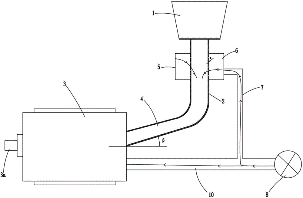
[0035] image 3 It is a schematic structural diagram of a feeding mechanism embodiment 2 of the present invention; as image 3 As shown, the components that are the same as or corresponding to those in the first embodiment are marked with the corresponding reference numerals in the first embodiment. For the sake of simplicity, only the differences from the first embodiment will be described below. This embodiment two and figure 2 The difference of the first shown embodiment is that this embodiment also includes an air induction channel 10 with one end in communication with the air inlet of the combustion chamber 3, the blower fan 8 is arranged at the other end of the air induction channel 10, and the air duct The end of 7 communicates with the air-inducing channel 10, and a part of the gas is introduced into the annular cavity 6 through the air duct 7 through the fan 8, and another part of the gas is introduced into the combustion chamber 3 through the air-inducing channel 1...
Embodiment 3
[0037] Figure 4 It is a schematic structural view of Embodiment 3 of a feeding mechanism of the present invention; as Figure 4 As shown, the parts that are the same as or corresponding to those in the second embodiment are marked with the corresponding reference numerals in the second embodiment. For the sake of simplicity, only the differences from the second embodiment will be described below. This embodiment three and image 3The difference of the second embodiment shown is that: the sleeve 5 is provided with a sleeve jacket 51, and the air inlet 51a of the sleeve jacket 51 passes through the flue gas delivery pipeline 11 and the high temperature of the combustion chamber 3 The flue gas outlet 3b communicates, and the gas outlet 51b of the sleeve jacket 51 communicates with the high-temperature flue gas inlet 3c of the combustion chamber 3 through the flue gas collection pipeline 12 . The flue gas delivery pipeline 11 in this embodiment is only a branch of the gas path ...
PUM
 Abstract
Description
Claims
Application Information
 - R&D
- Intellectual Property
- Life Sciences
- Materials
- Tech Scout
- Unparalleled Data Quality
- Higher Quality Content
- 60% Fewer Hallucinations
Browse by: Latest US Patents, China's latest patents, Technical Efficacy Thesaurus, Application Domain, Technology Topic, Popular Technical Reports.
© 2025 PatSnap. All rights reserved.Legal|Privacy policy|Modern Slavery Act Transparency Statement|Sitemap|About US| Contact US: help@patsnap.com


