Phase change cold accumulating device

A phase change cold storage and phase change material technology, applied in the field of heat exchange management, can solve problems such as unseen applications, achieve a wide range of applications, highlight substantial characteristics, and increase the effect of total heat absorption

Inactive Publication Date: 2015-08-12
INST OF APPLIED ELECTRONICS CHINA ACAD OF ENG PHYSICS
View PDF7 Cites 8 Cited by
  • Summary
  • Abstract
  • Description
  • Claims
  • Application Information

AI Technical Summary

Problems solved by technology

[0004] In 2003, Cao Jianguang and others carried out research on the application of aluminum foam in phase change energy storage devices, and obtained the law of partial phase change energy storage based on the enhanced heat transfer of aluminum foam, but this technology has not yet been applied.

Method used


Image

  • Phase change cold accumulating device
  • Phase change cold accumulating device

Examples


Embodiment 1

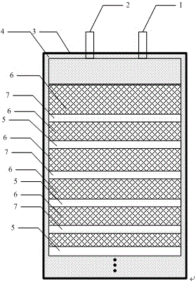
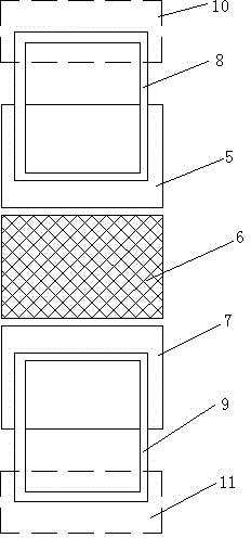
[0024] The invention includes a heat-taking cold plate, a heat-releasing cold plate, a skeleton material, a phase-change material, and a thermal insulation material arranged in a package casing; a skeleton material is arranged between the heat-taking cold plate and the heat-releasing cold plate; the skeleton material and The heat-releasing cold plate and the heat-taking cold plate are stacked and staggered in layers; the skeleton material is filled with phase-change materials; the inner wall of the package shell is provided with heat-insulating materials; A heat releasing circuit is arranged in the cold plate; a heat-taking refrigerant is arranged in the heat-taking circuit; a heat-releasing refrigerant is arranged in the heat-releasing circuit; an exhaust hole and a phase-change material filling port are arranged on the top of the packaging shell.

[0025] After absorbing the heat from the heat source, the heat-absorbing refrigerant enters the heat-extracting cold plate throug...

Embodiment 2

[0034] It is basically the same as Example 1, except that the size of the skeleton material is 135mm×270mm×40mm, and the number of layers is 2 layers.

[0035] Take the hot and cold plate as a copper plate, the number of layers is 1 layer, the section of the hot loop is circular, the inner diameter is 6mm, and the center distance of the hot loop is 38mm, and the hot and cold plate is connected to the hot loop through the interface pipe.

[0036] The heat release cold plate is a copper plate with 1 layer, the heat release circuit cross section is circular, the inner diameter is 6mm, and the center distance of the heat release circuit is 40mm. The heat release cold plate is connected to the heat release circuit through the interface pipe.

[0037] The phase change material is n-tetradecane, the filling volume is 2.0L, the expansion space accounts for 18% of the total effective volume of the regenerator, and the single cold storage capacity is 400kJ.

[0038] The phase change mat...

Embodiment 3

[0041] It is basically the same as Example 1, except that the skeleton material is HTC foamed graphite, the interlayer thermal conductivity is 245w / m K, the open porosity is 61%, the effective porosity is 95%, and the size is 152mm×194mm×25mm , the number of layers is 4 layers.

[0042] Take the hot and cold plate as an aluminum plate, the number of layers is 2 layers, the cross section of the hot circuit is circular, the inner diameter is 6mm, and the center distance of the hot circuit is 38mm, and the hot and cold plate is connected to the hot circuit through the interface pipe.

[0043] The heat release cold plate is an aluminum plate with 2 layers. The heat release circuit has a circular cross-section with an inner diameter of 6mm. The center distance of the heat release circuit is 40mm. The heat release cold plate is connected to the heat release circuit through an interface pipe.

[0044] The phase change material is n-hexadecane, the filling volume is 1.5L, the expansio...


PUM


Abstract

The invention provides a technical scheme of a phase change cold accumulating device. According to the scheme, the phase change cold accumulating device comprises a heat taking cold plate, a heat releasing cold plate, a framework material, a phase change material and a heat isolation material which are arranged in a package shell. The framework material is arranged between the heat taking cold plate and the heat releasing cold plate. The framework material, the heat releasing cold plate and the heat taking cold plate are arranged in a laminated stacking and staggered mode. The framework material is filled with the phase change material. The heat isolation material is arranged on the inner wall of the package shell. A heat taking loop is arranged in the heat taking cold plate. A heat releasing loop is arranged in the heat releasing cold plate. A heat taking secondary refrigerant is arranged in the heat taking loop. A heat releasing secondary refrigerant is arranged in the heat releasing loop. An exhaust hole and a phase change material adding port are formed in the top of the package shell. According to the scheme, the heat releasing loop, the heat taking loop and the phase change material are utilized for carrying out heat exchange, additional energy is not needed, and the whole device is small in size and low in energy consumption.

Description

technical field [0001] The invention relates to the field of heat exchange management, in particular to a phase change cold storage device. Background technique [0002] The research focus of thermal management technology is to solve the transfer process of heat from the heat source to the cooling medium under high heat flux in the "heat extraction loop", but the "heat release loop" and how to reduce the volume, weight and power consumption of the thermal management system have not yet been solved. draw enough attention. With the development of solid-state lasers in the direction of long-term and higher power, if the traditional micro-channel real-time water cooling method is still used, the volume, weight and power consumption of the thermal management system will be extremely large, which greatly limits high-power solid-state lasers. field of application. [0003] Phase change cold storage is a method of storing cold energy through phase change of phase change materials,...

Claims


Application Information

Patent Timeline
Patent Type & Authority Applications(China)
IPC IPC(8): F28D20/02
CPCY02E60/14
Inventor 范国滨张卫刘军王永振杨波柳丽卿蔡光明闫锋武德勇王姣谢秀芳李春领
Owner INST OF APPLIED ELECTRONICS CHINA ACAD OF ENG PHYSICS
Why Eureka
Try Eureka