High-heat-transmission solder tip suitable for soldering in small spaces

A soldering iron head and small space technology, applied in the direction of soldering iron, soldering station, welding equipment, etc., can solve the problems of unsatisfactory process, poor working conditions, long time, etc., meet reliability requirements, improve work efficiency, and ensure reasonable sexual effect

Active Publication Date: 2015-08-19
BEIJING INST OF CONTROL ENG
View PDF5 Cites 5 Cited by
  • Summary
  • Abstract
  • Description
  • Claims
  • Application Information

AI Technical Summary

Problems solved by technology

[0003] The packaging structure of the 3D-PLUS device leads to soldering. Generally, the tip of the soldering iron cannot reach the heel of the pin. In order to make the solder flow to the heel of the pin as much as possible, the measured temperature of the commonly used small horseshoe soldering iron tip reaches about 315°C, and the outer pins of the body are repeatedly heated. , the root of the solder joint (bend) is tin-free, such as Figure 4 As shown, it does not meet the requirements in ECSS-Q-ST-70-38C. The standard requires that the height of the solder joints should be higher than the upper surface of the lead legs. Compared with the recommended process, the 3D-PLUS assembly process takes a longer time and has a higher temperature. , still unable to form standard solder joints, but due to the limitation of the device package and the shape of the soldering iron, it has been unable to improve for a long time; at the same time, the soldering process is easy to form lead bridges, and because the soldering iron cannot penetrate below the device body, it is repaired after the bridge is formed very difficult
It can be seen that the process still does not meet the requirements, and the working conditions are poor

Method used


Image

  • High-heat-transmission solder tip suitable for soldering in small spaces
  • High-heat-transmission solder tip suitable for soldering in small spaces
  • High-heat-transmission solder tip suitable for soldering in small spaces

Examples


Embodiment Construction

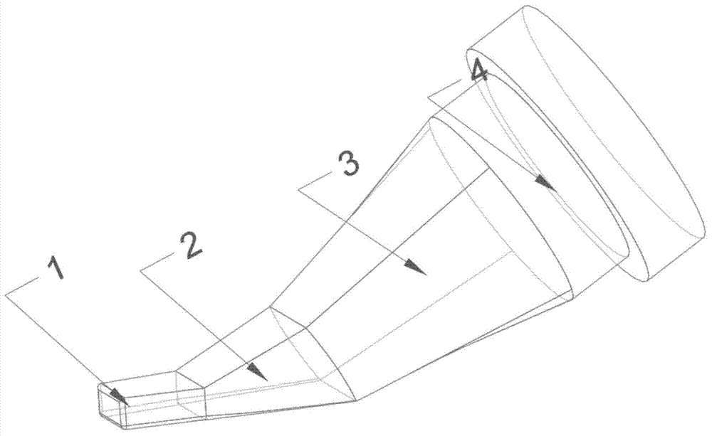
[0027] Such as figure 1 , 2 As shown, the present invention provides a high heat transmission soldering iron tip suitable for soldering in a small space, including: a tip 1, a first transition part 2, a second transition part 3 and a soldering iron assembly part 4;

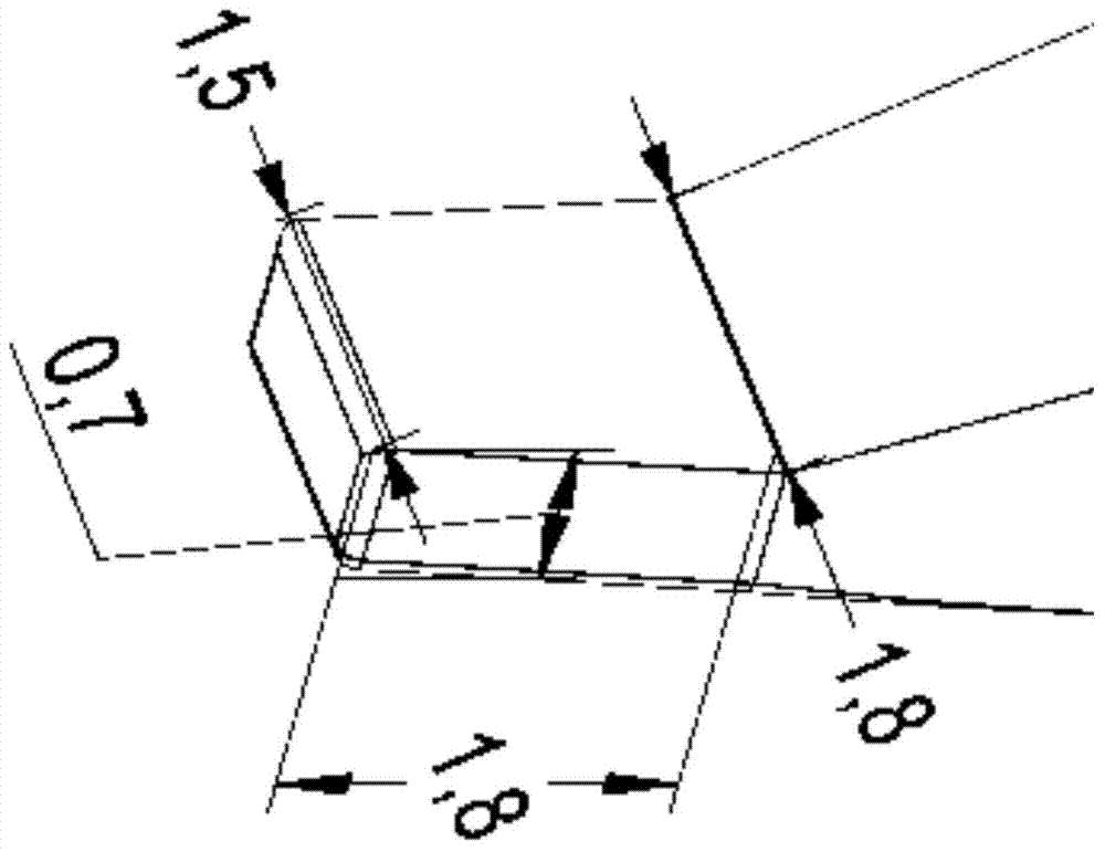
[0028] Both the head end face and the tail end face of the tip 1 are rectangular, the length of the long side of the head end rectangle is less than the length of the long side of the tail end rectangle, and the length of the wide side of the head end rectangle is equal to the width of the tail end rectangle, There is a uniform transition between the end surface of the head and the end surface of the tail, the shape of the bottom surface and the top surface of the tip 1 are the same, both are isosceles trapezoidal; the end surface of the tail of the tip 1 matches and is fixedly connected to the end surface of the head of the first transition part 2 , the tail of the first transition part 2 is connected to the he...


PUM


Abstract

Disclosed is a high-heat-transmission solder tip suitable for soldering in small spaces. The solder tip comprises four parts, namely a soldering iron assembly part, two transition parts and a tip part, the assembly part is designed according to a used soldering station, assembling use is guaranteed, the transition parts are as large as possible and short so as to reduce heat resistance and can be in smooth transition with the tip part, and the tip part is in key size and enabled to go deep into the bottom of a device for narrow gap soldering. A base material of the solder tip is red copper, the solder tip is sequentially and integrally plated with iron and nickel, the portions except for bottom soldering positions are plated with chrome, and the bottom soldering positions are bonded with tin. The solder tip can be used for narrow-gap and high-heat-transmission soldering at the same time, and the non-soldering positions of the device are prevented from being bonded with tin. The solder tip is particularly applicable to SOP packaged 3D-PLUS devices.

Description

technical field [0001] The invention is a high heat transmission soldering iron tip suitable for small space welding, especially suitable for small space welding of devices such as 3D-PLUS. Background technique [0002] With the development of high integration and miniaturization of aerospace electronic products, the application of 3D-PLUS devices is becoming more and more widespread. Manual soldering is required; 3D-PLUS device pins protrude from the bottom of the chip, which is a typical SOP device, in which the minimum lead center distance reaches 0.5mm, and the smaller the pin gap, the more difficult it is to solder. The device body is potted with epoxy resin material, the epoxy resin surface is nickel-plated, the nickel surface is gold-plated, and the circuit is formed by laser etching. During the assembly process, it is necessary to avoid sticking tin to the device body to prevent short circuit. 3D-PLUS recommends that the manual assembly process requires a soldering ...

Claims


Application Information

Patent Timeline
Patent Type & Authority Applications(China)
IPC IPC(8): B23K3/02
CPCB23K3/025
Inventor 王修利严贵生董芸松李思阳
Owner BEIJING INST OF CONTROL ENG
Why Eureka
Try Eureka