
System and method for testing function of protecting card

A technology for protection clips and functional testing, which is applied in the direction of measuring electricity, measuring devices, measuring electrical variables, etc., and can solve the problems of difficulty in accurately judging the performance of protection clips, increasing the workload of workers, and the risk of safe operation of nuclear power plants. The effect of reducing the risk of circuit failure, reducing the burden on staff, and reducing the risk of operation

Inactive Publication Date: 2015-08-19
CHINA GENERAL NUCLEAR POWER OPERATION +2
View PDF13 Cites 39 Cited by
  • Summary
  • Abstract
  • Description
  • Claims
  • Application Information

AI Technical Summary

Problems solved by technology

[0004] At present, most of the protection cards of nuclear power plants in operation in my country have been in operation for decades. During the long-term operation, the protection cards have a certain wear and tear, and their functions and performances have been reduced, which poses certain risks to the safe operation of nuclear power plants. ; In addition, the current nuclear power plant lacks effective detection devices for it, and it is difficult to accurately judge the performance of the protection card
In the prior art, the wiring is complicated in the function test of the protection card, requiring the staff to be very familiar with the function and principle of the protection card. Manual testing cannot realize the automatic monitoring of the whole process of the test, which increases the workload of the staff.

Method used


Image

  • System and method for testing function of protecting card
  • System and method for testing function of protecting card
  • System and method for testing function of protecting card

Examples


Embodiment Construction

[0049] In order to have a clearer understanding of the technical features, purposes and effects of the present invention, the specific implementation manners of the present invention will now be described in detail with reference to the accompanying drawings.

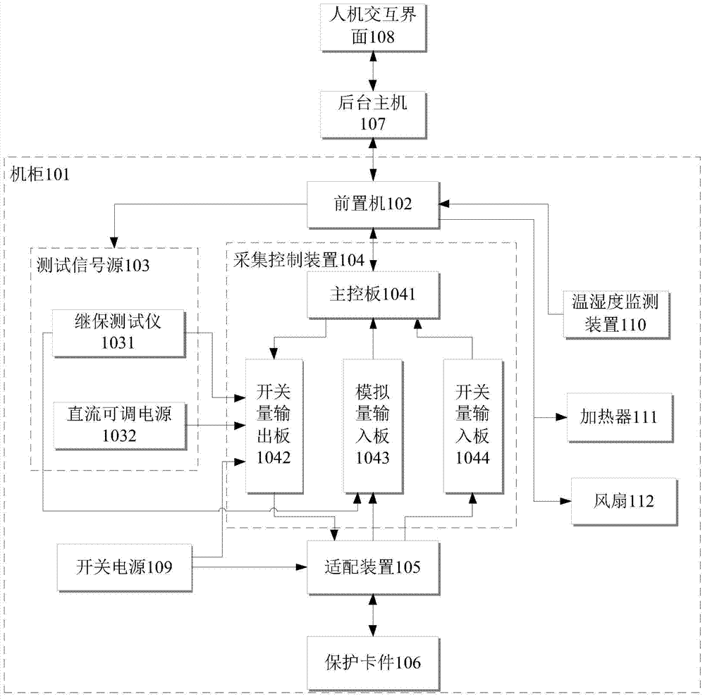
[0050] figure 1 Shown is a protection card function test system in some embodiments of the present invention, which is used to perform a function test on the protection card 106 . The protection card function test system includes a human-computer interaction interface 108, a background host 107, a front-end processor 102, a test signal source 103, an acquisition control device 104, an adapter device 105, a protection card 106, a switching power supply 109, and a temperature and humidity monitoring device 110, heater 111 and fan 112. Wherein, the protection card 106 is connected with the adapter device 105, and the switching power supply 109 supplies power to the protection card 106; the man-machine interface 108 sends th...


PUM


Abstract

The invention discloses a system and method for testing the function of a protecting card. The system comprises a front-end processor, a testing signal source, an acquisition control device, an adapting device, a switching power supply, a temperature and humidity monitoring device, a heater, and a fan. The front-end processor receives an environmental parameter of the temperature and humidity monitoring device and transmits a first adjusting signal and a second adjusting signal to the heater and the fan. The testing signal source receives a control instruction. The acquisition control device receives a control instruction. The temperature and humidity monitoring device detects an environmental parameter in the system for testing the function of the protecting card. The heater adjusts the temperature in the system for testing the function of the protecting card. The fan adjusts the temperature in the system for testing the function of the protecting card. The system and method for testing the function of the protecting card use an automated, intellectualized, and integrated online monitoring means and may accurately and high-efficiently test the function of the protecting card, and the temperature and humidity monitoring device, the heater, and the fan may adjust and control the environmental parameter in cooperation so as to provide an appropriate work environment for the devices.

Description

technical field [0001] The invention relates to the on-line monitoring technology of power equipment in nuclear power plants, in particular to a function testing system and method for protection cards of nuclear power plants. Background technique [0002] On-line digital status monitoring and monitoring technology of power equipment is the key technology of nuclear power plants. In nuclear power plants, a nuclear power plant board card detection technology platform is established through the development and establishment of functions and maintenance test methods, and the status maintenance and monitoring technology is applied to nuclear power plant electrical protection and control systems. In the field of functional testing of circuit boards, to realize the functional test management of nuclear power plant boards, improve the reliability and maintenance level of operating boards and spare parts of nuclear power plants, and ensure the safe operation of power plants. [0003]...

Claims


Application Information

Patent Timeline
IPC IPC(8): G01R31/00
Inventor 滕杰段贤稳刘斌胡振华白世杰许航源屈天龙
Owner CHINA GENERAL NUCLEAR POWER OPERATION
Learn More