Cement mixer capable of realizing automatic feeding and accurate discharging

A cement mixer and automatic feeding technology, which is applied in the direction of cement mixing device, unloading device, clay preparation device, etc. It can solve the problems that the material is not easy to be discharged, the angle of the mixing bucket cannot be adjusted, and the labor intensity is reduced, so as to achieve convenience. The effect of cleaning, reducing labor intensity and convenient loading

Active Publication Date: 2015-08-26
宜兴市青象水泥有限公司
View PDF5 Cites 2 Cited by
  • Summary
  • Abstract
  • Description
  • Claims
  • Application Information

AI Technical Summary

Problems solved by technology

[0004] The angle of the mixing barrel of the existing mixer cannot be adjusted. After the mixer is used, it needs to be cleaned. The internal materials are not easy to be removed, which will affect the next use. The existing mixer often causes the cement to fall on the ground during the discharge process. The main reason is that the control accuracy is low, and the outlet cannot be closed in time. At the same time, the feeding of the existing mixer basically relies on manpower, the feeding speed is slow, and the labor intensity is high. The market needs a mixer that can control the inclination angle of the mixing tank and facilitate cleaning. , at the same time, it can precisely control the discharge, reduce the waste of cement, improve the efficiency of discharge, and at the same time, the degree of automation of feeding can greatly reduce the labor intensity of labor

Method used


Image

  • Cement mixer capable of realizing automatic feeding and accurate discharging
  • Cement mixer capable of realizing automatic feeding and accurate discharging
  • Cement mixer capable of realizing automatic feeding and accurate discharging

Examples


Embodiment Construction

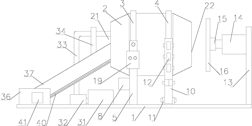
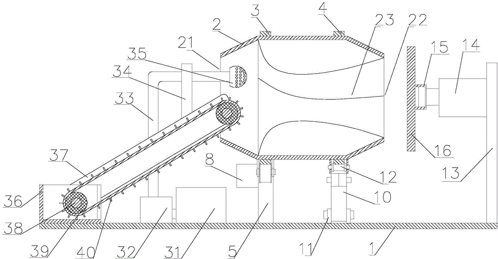
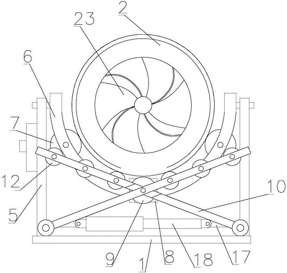
[0022] refer to figure 1 , figure 2 and image 3, an automatic feeding and precise discharging cement mixer of the present invention, comprising a base 1, a mixing bucket 2, a water tank 31, a water pump 32, a water pipe 33, a water pipe bracket 34, a water spray head 35, a batching box 36, side guards 37, transmission Material shaft 38, feed roller 39, conveyor belt 40, conveyor belt power motor 41, front guide rail 3, rear guide rail 4, front bracket 5, front bracket 6, front supporting wheel 7, stirring motor 8, power wheel 9, rear bracket 10 , inclination adjustment wheel 11, rear supporting wheel 12, end cover support 13, end cover hydraulic cylinder 14, end cover seat 15, end cover 16, hinged ear 17, inclination adjustment hydraulic cylinder 18 and electric control box 19, the base 1 The right side is provided with batching box 36, and described batching box 36 both sides are respectively provided with side guard plate 37, and described side guard plate 37 is equipped...


PUM

PropertyMeasurementUnit
heightaaaaaaaaaa

Abstract

The invention discloses a cement mixer capable of realizing automatic feeding and accurate discharging. The cement mixer includes an end cover hydraulic cylinder, an end cover seat, an end cover, hinge lugs, a tilt angle adjusting hydraulic cylinder and an electric control box, wherein side protective plates are respectively arranged on the two sides of a material matching box; two material conveying shafts are mounted on the side protective plates; the material conveying shafts are connected with a conveyor belt power motor; material conveying rollers are arranged on the material conveying shafts; a water pipe is arranged on a water pipe support; a sprinkler head is arranged at one end of the water pipe, and the other end of the water pipe is mounted on a water pump; a front bracket is hinged to and mounted on a front support, and the tilt angle adjusting wheel is arranged at the lower part of a rear support; the tilt angle adjusting wheel is in contact with a base; the hinge lugs are arranged at the upper part of the tilt angle adjusting wheel; the tilt angle adjusting hydraulic cylinder is hinged and mounted between the hinge lugs. The cement mixer provided by the invention can control the tilt angle of a mixing tank and is simple to operate; the mixing tank is easy to wash after being used, so that cement waste is avoided; in addition, the device is easy to operate, and the feeding automation degree is high, so that labor intensity of workers is greatly reduced.

Description

【Technical field】 [0001] The invention relates to the technical field of construction equipment, in particular to the technical field of an automatic feeding and precise discharging cement mixer. 【Background technique】 [0002] Modern architecture is inseparable from cement. Cement has a history of more than 300 years, and finally evolved into today's state. The mixture of early lime and volcanic ash is very similar to modern lime pozzolanic cement. It is used to bond concrete made of crushed stones and harden. Finally, it not only has high strength, but also can resist the erosion of fresh water or salt water. For a long time, it has been used as an important cementing material. In 1756, British engineer J. Smeaton discovered when studying the characteristics of some lime hardening in water: to obtain hydraulic lime, limestone containing clay must be used to burn system; masonry mortar for underwater construction, the most ideal composition is made of hydraulic lime and vo...

Claims


Application Information

Patent Timeline
Patent Type & Authority Applications(China)
IPC IPC(8): B28C5/12B28C7/14B28C7/04B28C7/16
CPCB28C5/12B28C7/04B28C7/14B28C7/16
Inventor 金烜伊
Owner 宜兴市青象水泥有限公司
Why Eureka
Try Eureka