Oilfield Waste Oil Recovery Electromagnetic Steam Integrated Device

A technology of sewage oil recovery and integrated device, applied in steam generation, steam generation method, water/sewage multi-stage treatment, etc., can solve the problems of affecting liquid flow, low heating efficiency, low head pressure, etc. The effect of fast heating speed and high external pressure

Active Publication Date: 2018-09-04
马洪发
View PDF1 Cites 0 Cited by
  • Summary
  • Abstract
  • Description
  • Claims
  • Application Information

AI Technical Summary

Problems solved by technology

At present, the general problems of the general waste oil recovery device are: the suction is small, the pump is often damaged, the output pressure is low, and the crude oil solidifies and blocks the pipeline in winter, etc.
The blower must bring in a large amount of cold air to suck in the oily sewage, which affects the flow of the sucked liquid. Moreover, in winter, the crude oil is quickly solidified and blocked the pipeline due to the inhalation of a large amount of cold air. The softening of crude oil affects the export; the vacuum pump cannot adapt to the fluid with sediment, and the pump is frequently damaged
Multi-stage centrifugal pumps are mostly used in the export section, with high power, but the head pressure is low, the export is difficult, and it is often blocked during winter use
[0003] At present, the common heating system in the tank has low heating efficiency, and a separate steam generator is used for the steam used in the well site, which has a large transportation volume, occupies a large area of ​​land and requires a large investment

Method used


Image

  • Oilfield Waste Oil Recovery Electromagnetic Steam Integrated Device
  • Oilfield Waste Oil Recovery Electromagnetic Steam Integrated Device
  • Oilfield Waste Oil Recovery Electromagnetic Steam Integrated Device

Examples


Embodiment Construction

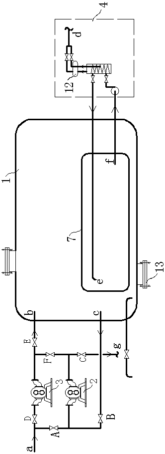
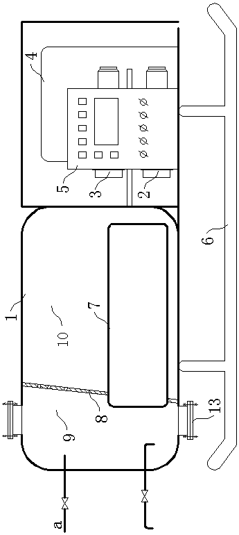
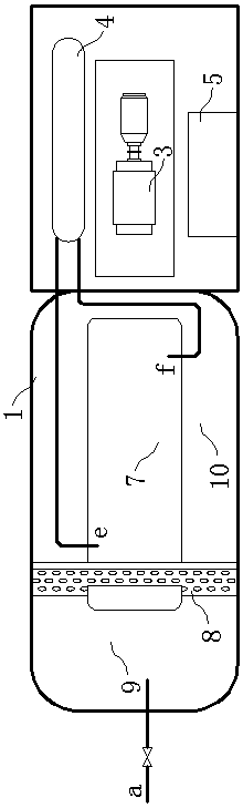
[0016] Below in conjunction with accompanying drawing, the oilfield waste oil reclaiming electromagnetic steam integrated device of the present invention is further described:

[0017] The electromagnetic steam integrated device for recovering oilfield waste oil of the present invention is composed of a waste oil treatment tank 1 , a material pump I2 , a material pump II3 , a boiler 4 and an instrument control box 5 .

[0018] The waste oil treatment tank 1, the material pump I2, the material pump II3, the boiler 4 and the instrument control box 5 are assembled on the flat plate of the skid base 6, and the waste oil treatment tank 1, The instrument control box 5, the material pump I2, the material pump II3 and the boiler 4 are installed side by side at the other end in sequence, and the waste oil treatment tank 1 at the front end is adjacent to each other. Wherein the material pump I2, the material pump II3, the boiler 4 and the instrument control box 5 can also be centrally a...


PUM


Abstract

The invention provides an electromagnetic vapor collection device for dirty oil recovery in an oil field and relates to an oil field dirty oil treatment device. A dirty oil treatment tank, a material pump I, a material pump II, a boiler and an instrument control cabinet are integrated on a flat plate of a skid seat; the material pump I and the material pump II adopt parallel-connection pipelines, front-end pipelines of the material pumps I and II are connected with a material inlet a and rear pipelines of the material pumps I and II are connected with a raw material middle inlet b and a sewage bottom outlet c of the dirty oil treatment tank; a hot water heater is arranged at the bottom in the dirty oil treatment tank, and a hot water inlet e and a water return outlet f of the hot water heater are connected with an outlet and an inlet of the boiler respectively. Eight functions including suction, outward discharging, simultaneous discharging and sucking, direct discharging with no dirty oil passing through the tank, self-circulation cooling protection, backwashing of suction pipelines, heating and heat tracing of dirty oil and sewage in a dirty oil tank and washing of machine tools in a well site can be achieved; the suction force of the device is large, the device can be applied to a large-viscosity oil-water mixed liquid containing mud and sand, the outward conveying pressure is high, meanwhile, the heating speed of an electromagnetic heat tracing system is high, and the whole device can meet on-site work requirements completely.

Description

technical field [0001] The invention relates to an oil field waste oil treatment device, in particular to an oil field waste oil recycling electromagnetic steam integration device. Background technique [0002] There will be a large amount of dirty oil and sewage falling to the ground during oilfield well site operations. Because of the mixture of dirty oil and sewage, crude oil and sediment, how to recycle it has always been a difficult problem. At present, the common problems of the general waste oil recovery device are: low suction, frequent damage to the pump, low output pressure, and blockage of pipelines due to solidification of crude oil in winter. And because the crude oil is flammable, the waste oil recovery device must be separated from the well site for a certain distance during operation, so the device must have a large suction force. In order to increase the suction, blowers or vacuum pumps are mostly used in the suction section of the waste oil recovery device...

Claims


Application Information

Patent Timeline
Patent Type & Authority Patents(China)
IPC IPC(8): C02F9/10B65D88/74F22B1/28
Inventor 崔小平姚红邵克勇李庆于宝水
Owner 马洪发
Why Eureka
Try Eureka