A steam-driven lubricating oil pump emergency oil supply system and method thereof
A lubricating oil pump and emergency oil supply technology, which is applied in the direction of engine components, engine starting, machine/engine, etc., can solve the problems that can not completely avoid malignant accidents and rely on electric drive, so as to improve safety production performance, prevent major accidents, The effect of ensuring reliability
- Summary
- Abstract
- Description
- Claims
- Application Information
AI Technical Summary
Problems solved by technology
Method used
Image

Examples
Embodiment 1
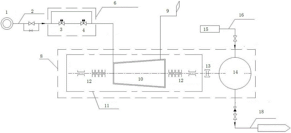
[0041] figure 1 Shown is the first embodiment of the present invention, the system includes an emergency steam source 1, a power failure emergency automatic start system 6, a drive steam turbine 11 and a centrifugal oil pump body 14, and the power failure emergency automatic start system 6 is arranged on the emergency steam source connected On the steam pipeline 2 of 1, the power-off emergency automatic start system 6 includes an electromagnetic-pneumatic linkage door and a quick-closing main steam valve 4 connected in series. The driving steam turbine 11 is connected on a shaft by coupling 13 and the oil pump body, and is installed on the steel base 8 together. Drive steam turbine 11, shaft coupling 13, centrifugal oil pump body 14 and related steam pipeline 2, oil inlet pipeline 16, oil supply pipeline, related valves, related instruments, etc. form a whole together with base 8, and the outer cover can be used to Sealed up, installed in the steam turbine workshop. It can a...
Embodiment 2
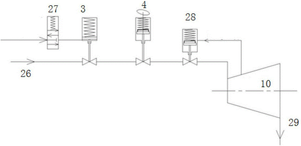
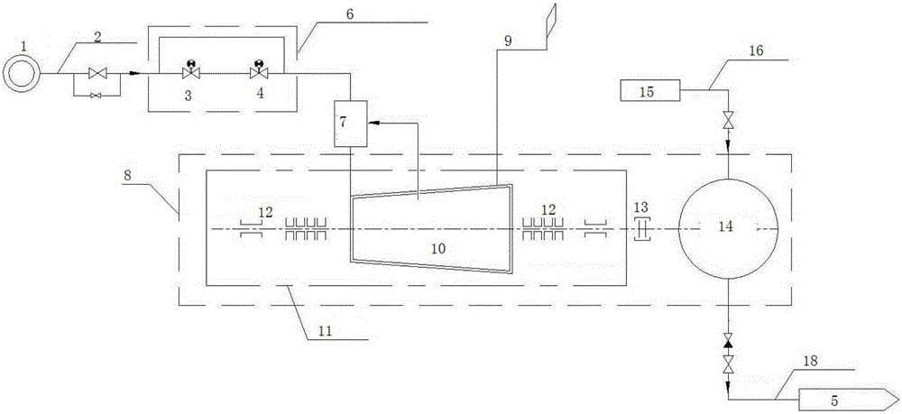
[0052] Such as figure 2 with image 3 As shown, in order to improve the reliability of the system, this embodiment adds a speed constant speed mechanism 7 to the emergency oil supply system of the above steam-driven lubricating oil pump. Between the steam ends, the speed constant speed mechanism 7 includes a steam inlet regulating valve, and the speed constant speed mechanism 7 uses the speed signal fed back by the steam turbine body 10 as a control signal to control and drive the steam turbine 11 by changing the opening degree of the steam inlet regulating valve. purpose of steam.
Embodiment 3
[0054] Such as Figure 4 As shown, the system is further equipped with an experimental system to ensure that the system can be put into operation at any time. In the experimental system, a circulation loop is set at the outlet of the emergency oil pump, which is connected to the main oil tank of the original steam turbine. Ensure that an independent circuit is formed between the outlet and inlet of the centrifugal oil pump during the experiment, which does not affect the safe operation of the lubricating oil system of the original steam turbine.
[0055] Wherein, the experimental system includes an experimental oil tank 17, a self-circulating lubricating oil pipeline, a check door and a manual gate.
[0056] On the inlet and outlet pipelines of the emergency gasoline-driven oil pump, the experimental pipelines are respectively connected to form self-circulating lubricating oil pipelines, which are all connected to the experimental oil tank 17. The specific layout of the inlet...
PUM
 Abstract
Description
Claims
Application Information
 - R&D
- Intellectual Property
- Life Sciences
- Materials
- Tech Scout
- Unparalleled Data Quality
- Higher Quality Content
- 60% Fewer Hallucinations
Browse by: Latest US Patents, China's latest patents, Technical Efficacy Thesaurus, Application Domain, Technology Topic, Popular Technical Reports.
© 2025 PatSnap. All rights reserved.Legal|Privacy policy|Modern Slavery Act Transparency Statement|Sitemap|About US| Contact US: help@patsnap.com