Car electric fan control method and system

A fan control and fan technology, which is used in the control of coolant flow, engine components, machines/engines, etc., can solve the problems of large engine energy consumption and large fan air volume, etc., to reduce energy consumption, improve safety performance, and stabilize water temperature. Effect

Inactive Publication Date: 2015-08-26
BEIJING BORGWARD AUTOMOBILE CO LTD
View PDF9 Cites 17 Cited by
  • Summary
  • Abstract
  • Description
  • Claims
  • Application Information

AI Technical Summary

Problems solved by technology

[0004] For this reason, the technical problem to be solved by the present invention is that the control of the electric fan in the prior art is determined according to the water temperature of the engine, the air volume of the fan is too large, and the energy consumption of the engine is large. Vehicle fan control method and system for maintaining machine water temperature in optimal working range and reducing fuel consumption

Method used


Image

  • Car electric fan control method and system
  • Car electric fan control method and system
  • Car electric fan control method and system

Examples


Embodiment 1

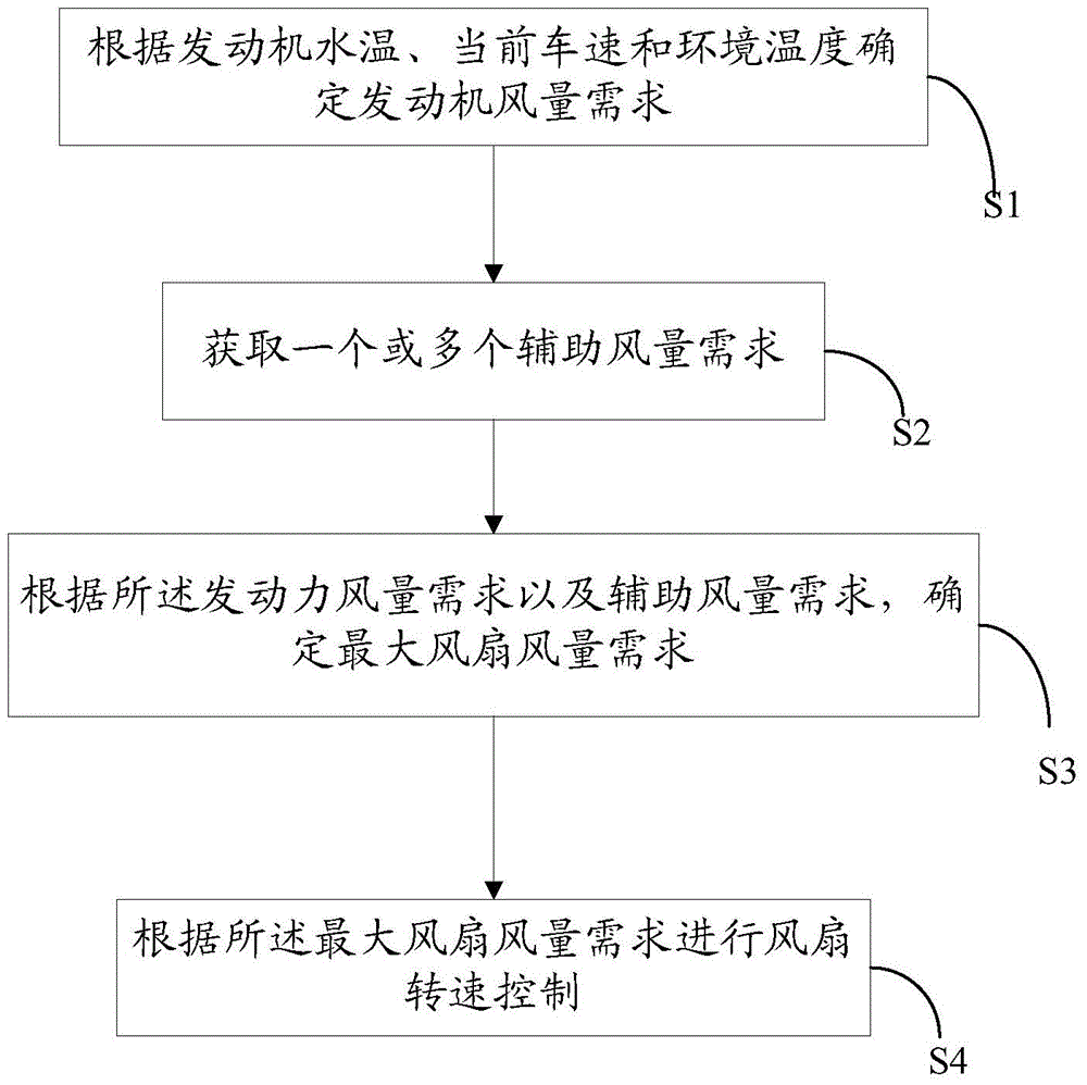
[0052] In this embodiment, a vehicle fan control method is provided, such as figure 1 shown, including the following steps

[0053] S1: Determine the engine air volume requirement according to the engine water temperature, current vehicle speed and ambient temperature.

[0054] Firstly, the mapping relationship of the air volume demand corresponding to the vehicle speed, ambient temperature and engine water temperature is established in advance, and then the air volume demand under the current vehicle speed, current ambient temperature and current engine water temperature is obtained as the engine air volume demand by looking up the table.

[0055]When establishing the mapping relationship of the air volume demand corresponding to the vehicle speed, ambient temperature and engine water temperature, first divide the vehicle speed into multiple ranges; then establish the air volume demand duty cycle corresponding to the ambient temperature and engine temperature within each spee...

Embodiment 2

[0070] In this embodiment, on the basis of the above-mentioned embodiment 1, a specific implementation manner of fan speed control according to the maximum fan air volume requirement is further provided, including the following process:

[0071] S51: Determine the required fan speed according to the maximum fan air volume requirement, and correct the required fan speed according to the fan resonance noise speed to obtain a corrected speed.

[0072] S52: Obtain the required duty cycle of the fan according to the corrected rotational speed;

[0073] S53: after taking the larger required duty ratio of the fan and the required duty ratio of the air conditioner, correcting the battery voltage, and then processing the maximum and minimum rotational speed limits of the fan to obtain the final fan duty ratio;

[0074] S54: Send the final duty cycle of the fan to the controller of the fan to control the operation of the fan.

[0075] In this solution, the required fan speed is correct...

Embodiment 3

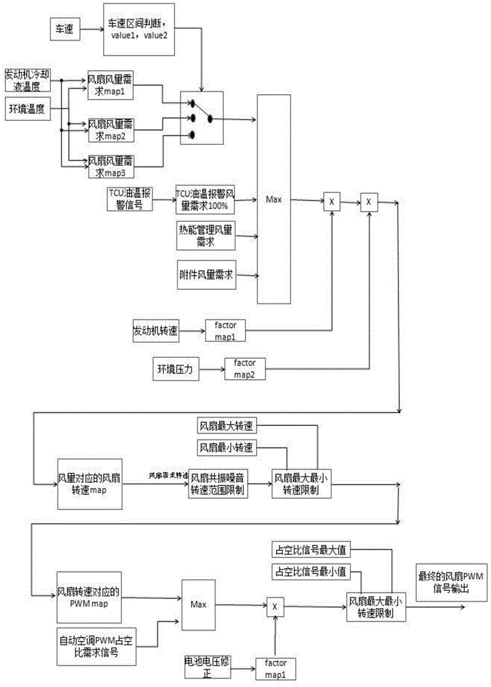
[0077] In this embodiment, a vehicle fan control method is provided, such as figure 2 As shown, the engine control unit ECU divides the fan air volume demand into three map level ranges according to the vehicle speed through the determination of the vehicle speed range, in which each map forms a table according to the engine water temperature and the ambient temperature, and the engine control unit ECU according to the map Find out the duty cycle at this engine speed, ambient temperature and engine water temperature. At the same time, the engine ECU calculates the maximum fan air volume duty cycle based on the four factors of TCU oil temperature alarm signal air volume demand, thermal energy management air volume demand, accessory air volume demand, and engine fan demand. The air volume duty ratio of the fan is then corrected according to the engine speed and ambient pressure. The correction here is verified by experiments. The corresponding speed is obtained through the fan ...


PUM


Abstract

The invention provides a car fan control method and system. The method comprises the following steps: determining transmitter air volume requirements according to transmitter water temperature, current vehicle speed and environment temperature; combining auxiliary air volume requirement signals, such as gearbox oil temperature signal air volume requirements, heat energy management air volume requirements and attachment air volume requirements, according to the transmitter air volume requirements; determining the maximal fan air volume requirements to obtain the fan requirement rotating speed so as to control the fan. According to the scheme, the vehicle speed, the engine cooling liquid temperature and the environment temperature are used as the main factors for fan control, and meanwhile the gearbox oil temperature, the heat energy management and other attachments are combined to accurately control the rotating speed of the electric fan, so that the fan is in the low-speed operating state as far as possible, the water temperature of the engine is stable, the engine can work in the optimum operating temperature, and the functions of saving fuel and reducing emission are achieved.

Description

technical field [0001] The invention relates to the field of automobiles, in particular to a method for controlling an electric fan used in a vehicle. Background technique [0002] In order for the vehicle to run normally, the engine needs to be cooled, and water cooling is generally used. This water-cooling method needs to set up a radiator, which is connected to the engine through a circulation pipe, and water is injected into the circulation pipe during operation, and the water is used to conduct heat. In order to ensure the heat dissipation effect, a fan needs to be provided to blow air on the surface of the radiator. At present, electronic fans are commonly used, also known as electric fans. This fan is characterized by a controller, which is usually a transmitter controller, also known as an ECU, which can receive water temperature signals and control them according to the water temperature signals. Electronic fan speed to achieve engine cooling balance, the fan spee...

Claims


Application Information

Patent Timeline
Patent Type & Authority Applications(China)
IPC IPC(8): F01P7/04
Inventor 卜江华王忠亮曲栋良
Owner BEIJING BORGWARD AUTOMOBILE CO LTD
Why Eureka
Try Eureka