
Mechanical seal device for high-temperature and high-pressure forced hot water circulating pump

The technology of a mechanical sealing device and a hot water circulating pump is applied to the components, mechanical equipment, pumps, etc. of the pumping device used for elastic fluid, which can solve the problems of unsatisfactory use effect, short service life and high maintenance cost, and achieves the The effect of reducing the temperature, increasing the life, and improving the cooling effect

Inactive Publication Date: 2015-08-26
SHANDONG IRON & STEEL CO LTD
View PDF9 Cites 5 Cited by
  • Summary
  • Abstract
  • Description
  • Claims
  • Application Information

AI Technical Summary

Problems solved by technology

[0005] The purpose of the present invention is to solve the above-mentioned problems in the prior art, and provide a mechanical seal device for a high-temperature and high-pressure forced hot water circulation pump, which solves the unsatisfactory use effect, high maintenance cost, short service life and high price in the prior art. technical issues

Method used


Image

  • Mechanical seal device for high-temperature and high-pressure forced hot water circulating pump
  • Mechanical seal device for high-temperature and high-pressure forced hot water circulating pump
  • Mechanical seal device for high-temperature and high-pressure forced hot water circulating pump

Examples


Embodiment Construction

[0028] The principles and features of the present invention are described below in conjunction with the accompanying drawings, and the examples given are only used to explain the present invention, and are not intended to limit the scope of the present invention.

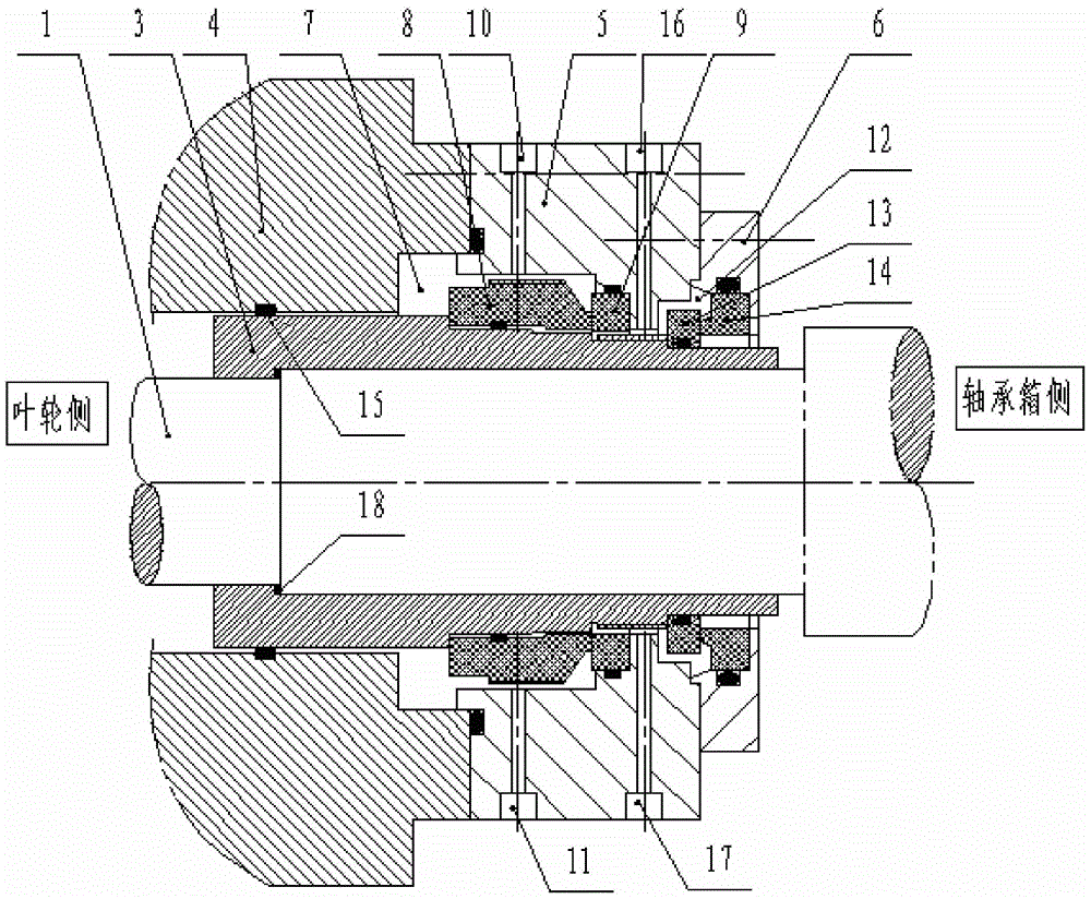
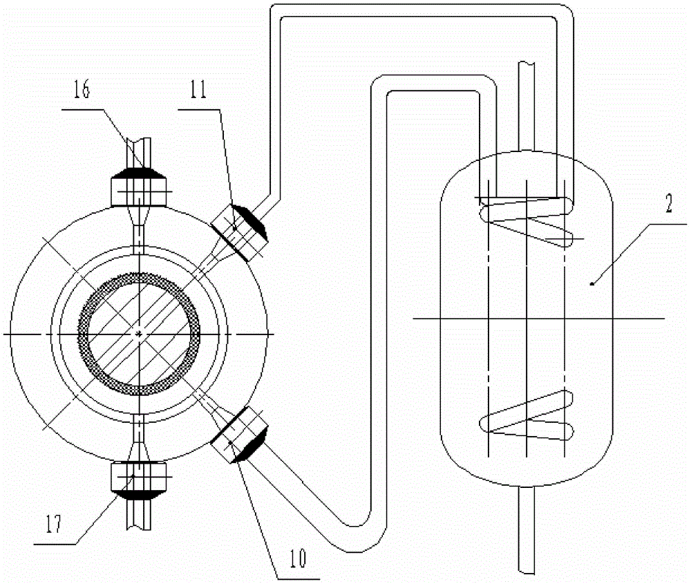
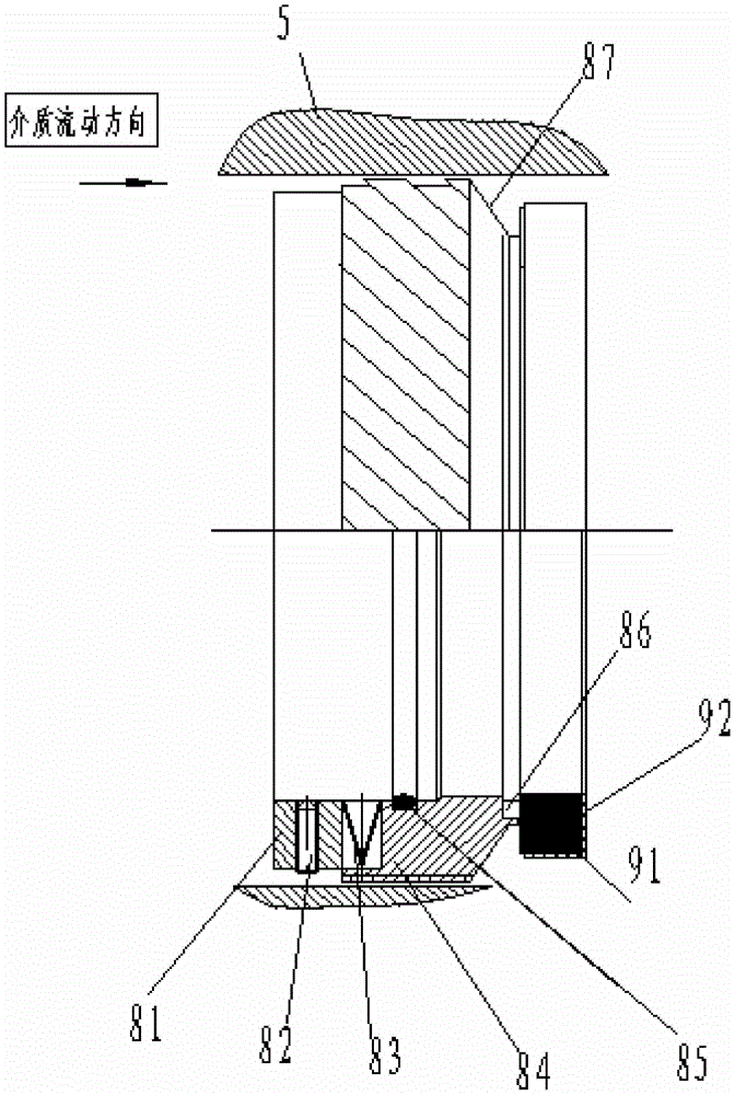
[0029] Such as Figures 1 to 4 As shown, a mechanical seal device for a high-temperature and high-pressure forced hot water circulation pump includes a pump shaft 1 and a heat exchanger 2. The pump shaft 1 is fitted with a pump shaft sleeve 3 on the impeller side close to the high-temperature and high-pressure hot water medium. The end face of the pump shaft 1 and the pump shaft sleeve 3 is matched with an O-ring 18, the pump shaft sleeve 3 is connected to the pump cover 4, and the pump cover 4 is connected to the main stage on the side of the bearing box away from the impeller. The seal seat 5 is connected, and the outer end of the primary seal seat 5 is provided with a secondary seal seat 6, and a sealing cavity 7...


PUM


Abstract

The invention discloses a mechanical seal device for a high-temperature and high-pressure forced hot water circulating pump. The mechanical seal device comprises a pump shaft and a heat exchanger. The pump shaft is provided with a pump shaft sleeve, the pump shaft sleeve is connected with a pump cover, the pump cover is connected with a primary seal base, and a secondary seal base is arranged at the tail end of the outer side of the primary seal base. A first seal cavity is formed between the primary seal base and the pump shaft sleeve, and a primary seal movable structure with a thread pump and a primary seal static structure with a thread pump are arranged in the first seal cavity. The primary seal base is provided with an internal circulation liquid inlet and an internal circulation liquid outlet, and the internal circulation liquid inlet and the internal circulation liquid outlet are communicated with the heat exchanger. A second seal cavity is formed between the secondary seal base and the pump shaft sleeve, and a secondary seal movable structure and a secondary seal static structure are arranged in the second seal cavity. The primary seal base is provided with a cooling water external circulation liquid inlet and a cooling water external circulation liquid outlet, and cooling water is provided by a power plant clear water pipeline. The technical problems that in the prior art, the using effect is unsatisfactory, the maintenance cost is high, the service life is short, and the price is high are solved.

Description

technical field [0001] The invention relates to the technical field of hot water circulating pumps, in particular to a mechanical seal device for high temperature and high pressure forced hot water circulating pumps. Background technique [0002] In the prior art, high temperature and high pressure forced hot water circulating pumps are widely used in metallurgy, electric power, textile, petroleum, chemical industry, rubber, heating and other system fields, to transport high temperature and high pressure hot water and those whose physical and chemical properties are similar to water liquid medium. High-temperature hot water is easy to produce vaporization, which will cause the liquid film on the end face of the mechanical seal to be destroyed, and make the contact end faces of the dynamic and static rings in a semi-dry friction or dry friction state, which will easily cause wear on the two contact end faces, resulting in seal failure and reduced life. At the same time, due ...

Claims


Application Information

Patent Timeline
IPC IPC(8): F04D29/08F04D29/10F04D29/58
Inventor 马学者邓扬玉孙冠功王东程涛秦栋夏永青王树
Owner SHANDONG IRON & STEEL CO LTD
Learn More