A botdr optical fiber strain distribution curve splicing method

A strain distribution and distribution curve technology, applied in the direction of using optical devices, special data processing applications, measuring devices, etc., can solve the problems of long time-consuming manual splicing, long testing distance, high cost, and improve splicing efficiency and splicing accuracy. Achieve test accuracy and reduce labor costs

Active Publication Date: 2017-08-29
CHINA ELECTRONIS TECH INSTR CO LTD
View PDF4 Cites 0 Cited by
  • Summary
  • Abstract
  • Description
  • Claims
  • Application Information

AI Technical Summary

Problems solved by technology

[0004] However, at present, the splicing of the BOTDR strain curves at both ends of the optical fiber can only be done manually, by manually finding the overlapping area of ​​the strain curves at both ends, and then manually splicing the two sets of strain curves. Due to the long test distance, the difference between the two measured strain curves The signal-to-noise ratio of the terminal data is very low, the noise is very high, the manual splicing takes a long time, the cost is high, and the error is large, which greatly affects the BOTDR product’s ability to test the strain distribution of ultra-long-distance optical fibers and the strain distribution of ultra-long-distance optical fibers. Promotion and Application of Distribution Testing Field

Method used


Image

  • A botdr optical fiber strain distribution curve splicing method
  • A botdr optical fiber strain distribution curve splicing method
  • A botdr optical fiber strain distribution curve splicing method

Examples


Embodiment Construction

[0041] Below in conjunction with accompanying drawing and specific embodiment the present invention is described in further detail:

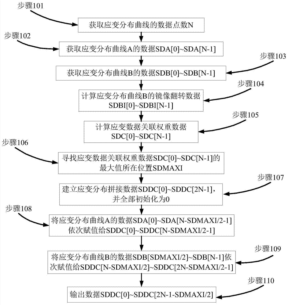
[0042] combine figure 1 As shown, a BOTDR optical fiber strain distribution curve splicing method includes the following steps:

[0043] Step 101. Obtain the number N of data points of the strain distribution curve.

[0044] Step 102, acquiring data SDA[0]˜SDA[N-1] of the strain distribution curve A.

[0045] Step 103, acquiring the data SDB[0]˜SDB[N-1] of the strain distribution curve B.

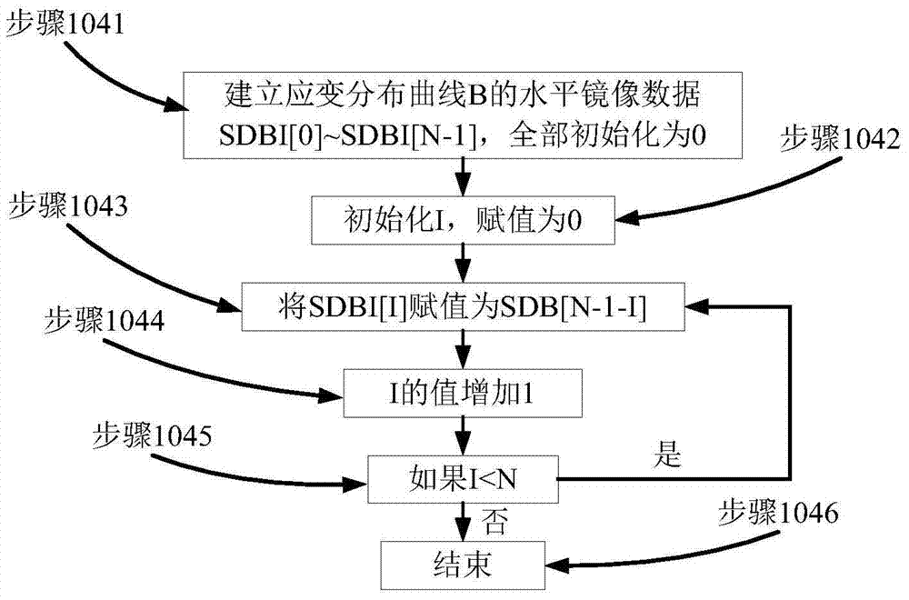
[0046] Step 104, calculating the mirror flip data SDBI[0]˜SDBI[N-1] of the strain distribution curve B.

[0047] Such as figure 2 As shown, the calculation method of the mirror flip data of the strain distribution curve B is as follows:

[0048] Step 1041, establish the horizontal image data SDBI[0]~SDBI[N-1] of the strain distribution curve B, all of which are initialized to 0;

[0049] Step 1042, initialize I and assign a value of 0;

[0050] Step 1...


PUM


Abstract

The invention discloses a BOTDR optical fiber strain distribution curve splicing method. The method uses a strain data associated weight calculation method as the core and utilizes a sliding quotient solving weight integral to seek a superposed area of strain curves of two optical fibers according to strain data coincidence similarity characteristics obtained after the two ends of each optical fiber are tested, so that automatic splicing of the strain curves is realized, the influence of optical fiber tail end strain data with the lower signal noise ratio to the curve splicing is effectively reduced, the optical fiber strain distribution data splicing efficiency and splicing accuracy are greatly improved, the labor cost is reduced, the test distance of a BOTDR product is lengthened, the measuring accuracy of strain distribution of super-long distance optical fibers is ensured, and the application field of the BOTDR product is widened.

Description

technical field [0001] The invention relates to a method for splicing BOTDR optical fiber strain distribution curves. Background technique [0002] The Brillouin Optical Time Domain Reflectometer (BOTDR) calculates the strain distribution of the optical fiber by measuring the Brillouin frequency shift distribution of the Brillouin backscattered light in the optical fiber. The pulsed light is incident from one end of the optical fiber at a certain frequency, and the incident pulsed light After interacting with the phonons in the fiber, Brillouin scattering occurs, and the back Brillouin scattered light returns to the incident end along the original path of the fiber. Since there is a linear relationship between the frequency shift of the Brillouin scattered light in the fiber and the axial strain and temperature of the fiber, the strain distribution in the fiber can be calculated by measuring the Brillouin scattered frequency shift distribution of the fiber. Brillouin optica...

Claims


Application Information

Patent Timeline
Patent Type & Authority Patents(China)
IPC IPC(8): G06F19/00G01B11/16
Inventor 袁明李立功闫继送张志辉陈晓峰
Owner CHINA ELECTRONIS TECH INSTR CO LTD
Why Eureka
Try Eureka