A gas flow field for a proton exchange membrane fuel cell

A proton exchange membrane and fuel cell technology, which is applied to fuel cell parts, collectors/separators, etc., can solve problems such as water removal, uneven gas distribution, and large reaction gas resistance that affect the gas mass transfer in the cell. To achieve the effect of simple structure, uniform gas distribution and small pressure loss

Active Publication Date: 2017-08-01
KUSN FUERSAI ENERGY
View PDF5 Cites 0 Cited by
  • Summary
  • Abstract
  • Description
  • Claims
  • Application Information

AI Technical Summary

Problems solved by technology

The mesh flow field has a simple structure and uniform gas distribution, but the resistance drop is relatively large. At the same time, if the metal material is used, there will be a large corrosion problem; the parallel groove flow field is currently the most used gas flow field. It has a simple structure and is easy to process. And the resistance drop is small, but there are problems in gas distribution, especially at high current densities, the gas distribution is seriously uneven, which affects the gas mass transfer and the removal of generated water during the battery reaction; the serpentine flow field is relatively long due to the long flow field. There is a problem of large reaction gas resistance

Method used


Image

  • A gas flow field for a proton exchange membrane fuel cell
  • A gas flow field for a proton exchange membrane fuel cell
  • A gas flow field for a proton exchange membrane fuel cell

Examples


Embodiment Construction

[0021] Combine below Figure 1 to Figure 3 And further illustrate the technical solution of the present invention through specific examples.

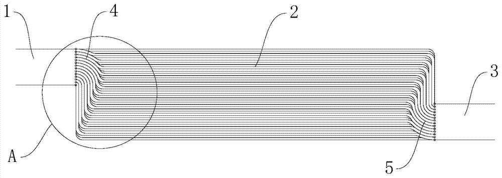
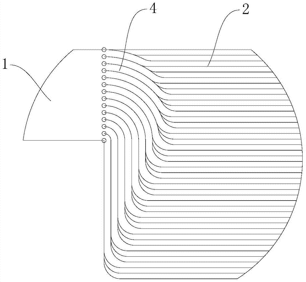
[0022] A gas flow field for a proton exchange membrane fuel cell, comprising a reaction gas inlet 1, a parallel groove flow field section 2 and a reaction gas outlet 3, and a first distribution device is arranged between the reaction gas inlet 1 and the parallel groove flow field section 2 The flow field section 4, the second distribution flow field section 5 is arranged between the reaction gas outlet 3 and the parallel groove flow field section 2, and the first distribution flow field section 4 and the second distribution flow field section 5 are formed by parallel streamlined grooves. The corners between the first distribution flow field section 4, the second distribution flow field section 5 and the parallel groove flow field section 2 are all streamlined, such as figure 1 and figure 2 shown. The first distribution flow field se...


PUM

PropertyMeasurementUnit
widthaaaaaaaaaa

Abstract

The invention discloses a gas flow field for a proton exchange membrane fuel cell. The gas flow field comprises a reaction gas inlet, a parallel groove flow field segment and a reaction gas outlet, wherein a first distribution flow field segment is arranged between the reaction gas inlet and the parallel groove flow field segment, a second distribution flow field segment is arranged between the reaction gas outlet and the parallel groove flow field segment, each of the first distribution flow field segment and the second distribution flow field segment consists of parallel streamlined grooves, and corners between the first distribution flow field segment and the parallel groove flow field segment as well as between the second distribution flow field segment and the parallel groove flow field segment are streamlined; each of the first distribution flow field segment and the second distribution flow field segment both consists of the parallel streamlined grooves, and the corners between the first distribution flow field segment and the parallel groove flow field segment as well as between the second distribution flow field segment and the parallel groove flow field segment are streamlined, so that the gas distribution is uniform, turbulence is not easy to form, the pressure loss is less, and discharging water and tail gas is facilitated. The gas flow field disclosed by the invention is simple in structure, uniform in the gas distribution, better in drainability and small in gas pressure loss.

Description

technical field [0001] The invention relates to the technical field of fuel cells, in particular to a gas flow field for a proton exchange membrane fuel cell. Background technique [0002] A fuel cell is a device that directly converts the chemical energy of fuel and oxidant into electrical energy through a chemical reaction. It has the outstanding advantages of fast start-up at room temperature, high energy conversion efficiency, little environmental pollution, and low noise. It is widely used in transportation, power generation, military , aerospace and other fields have broad application prospects. [0003] Proton Exchange Membrane Fuel Cell (PEMFC) uses perfluorosulfonic acid solid polymer as electrolyte, platinum / carbon or platinum-ruthenium / carbon as electrocatalyst, hydrogen or purified reformed gas as fuel, air Or pure oxygen is the oxidant, and graphite plates or surface-modified metal plates with gas flow channels are bipolar plates. [0004] The flow field is a ...

Claims


Application Information

Patent Timeline
Patent Type & Authority Patents(China)
IPC IPC(8): H01M8/026
CPCH01M8/026Y02E60/50
Inventor 顾荣鑫杨凤银张超章嵩松陶少龙靳宏建
Owner KUSN FUERSAI ENERGY
Why Eureka
Try Eureka