Broadband antenna

A broadband antenna and wireless communication device technology, applied in slot antennas, antenna grounding switch structure connection, radiating element structure form and other directions, can solve the problems such as the difficulty of reducing the size of the antenna, the difficulty of impedance matching, and being easily affected by the environment, so as to reduce the size of the antenna. Size, increase the antenna bandwidth, improve the effect of radiation efficiency

Inactive Publication Date: 2015-08-26
WISTRON NEWEB
View PDF9 Cites 10 Cited by
  • Summary
  • Abstract
  • Description
  • Claims
  • Application Information

AI Technical Summary

Problems solved by technology

Among them, the planar inverted F antenna has conductive pins to assist in impedance matching, but requires a large extension space to achieve wider bandwidth and better antenna radiation performance, while the coupled antenna is usually small in size, but is easily affected by the environment , and it is not easy to perform impedance matching
[0004] On the other hand, although the loop antenna (Loop Antenna) can more e

Method used


Image

  • Broadband antenna
  • Broadband antenna
  • Broadband antenna

Examples


Embodiment Construction

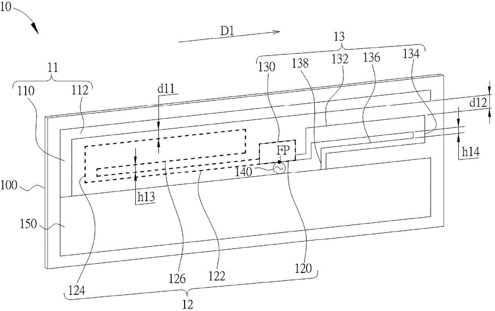
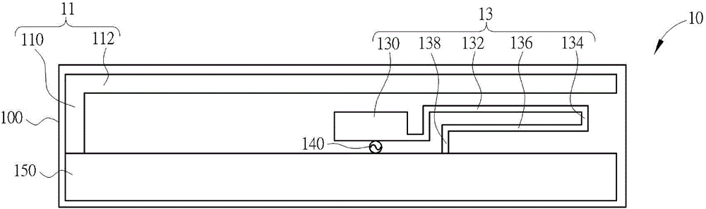
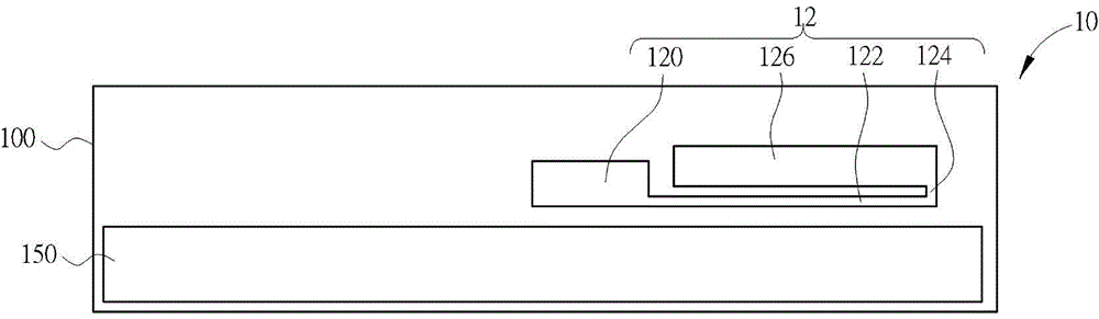
[0049] Please refer to Figure 1A to Figure 1E , Figure 1A It is a three-dimensional schematic diagram of a broadband antenna 10 according to an embodiment of the present invention, Figure 1B is a schematic front view of the broadband antenna 10, Figure 1C is a schematic view of the reverse side of the broadband antenna 10, Figure 1D is a schematic diagram of the voltage standing wave ratio of the broadband antenna 10, Figure 1Eis a schematic diagram of the radiation efficiency of the broadband antenna 10 . The broadband antenna 10 can be used in a wireless communication device to transmit and receive broadband or wireless signals of different frequency bands, such as signals of LTE wireless communication system (the frequency bands are generally between 704MHz-960MHz and 1710MHz-2700MHz). The broadband antenna 10 includes a substrate 100 , a first radiator 11 , a second radiator 12 , a third radiator 13 , a signal feeding component 140 and a grounding component 150 . ...


PUM


Abstract

The invention provides a broadband antenna. The broadband antenna is applied to a wireless communication device, and comprises a substrate, a grounding assembly, a first radiator, a second radiator, a third radiator and a signal feed-in assembly, wherein the grounding assembly is used for providing grounding; the first radiator comprises a first sector and a second sector, the first sector is connected with the second sector and approximately vertical to the second sector, the first sector is electrically connected with the grounding assembly, and the second sector extends along a direction; the second radiator is coupled with the first radiator; both ends of the third radiator are respectively and electrically connected with the second radiator and the grounding assembly; the signal feed-in assembly is electrically connected with the third radiator for transmitting or receiving RF signals; and the first radiator, the second radiator and the third radiator are arranged in a manner that the first radiator, the second radiator and the third radiator are sequentially formed on the substrate along the direction in the order of the first sector of the first radiator, the second radiator and the third radiator. The broadband antenna can increase the antenna bandwidth, improve the radiation efficiency and reduce the antenna size, can conform to specifications of a safety specification SAR at all operating frequency bands, and can be suitable for wireless communication systems of various kinds of different frequency bands.

Description

technical field [0001] The invention refers to a broadband antenna, in particular to a miniature broadband antenna with high radiation efficiency and compliance with safety regulations. Background technique [0002] As mobile devices with wireless communication functions (such as tablet computers, notebook computers, mobile phones, etc.) become indispensable daily tools for people, the application of wireless networks is increasing, and people's demand for transmission rates is also increasing. With the rise of Long Term Evolution (LTE), the demand for antenna bandwidth increases, and theoretically, the size of the antenna also needs to be increased accordingly. However, the appearance and size of wireless communication products are light and thin, and the antenna is relatively close to the human body. Therefore, the safety specification SAR (Specific Absorption Rate, specific absorption rate) has become a necessary consideration when designing antennas. In order to comply ...

Claims


Application Information

Patent Timeline
IPC IPC(8): H01Q1/50H01Q13/10H01Q1/36H01Q1/38
Inventor 游上贤黄健庭王志铭
Owner WISTRON NEWEB
Why Eureka
Try Eureka