
Current transformer protection device with remote short message alarming function

A technology for current transformers and SMS alarms, which is applied to emergency protection circuit devices, emergency protection circuit devices, and circuit devices for limiting overcurrent/overvoltage, and can solve the problem of small overcurrent and large ripple coefficient of photoelectric coupling elements , Transistor T7 burning and other problems, to achieve the effect of not easy to misoperation, safe protection and good stability

Active Publication Date: 2015-08-26
STATE GRID CORP OF CHINA +1
View PDF10 Cites 0 Cited by
  • Summary
  • Abstract
  • Description
  • Claims
  • Application Information

AI Technical Summary

Problems solved by technology

However, the voltage detection circuit of this device adopts bridge rectification, the ripple coefficient is large, the sampling voltage stability is not good, and it is easy to cause malfunction; due to the small overcurrent of the photoelectric coupling element, it is easy to be damaged by high voltage or surge breakdown. After the triode is turned on, because it cannot suppress and absorb the reverse electromotive force, it is easy to cause the triode T7 to heat up and burn out

Method used


Image

  • Current transformer protection device with remote short message alarming function
  • Current transformer protection device with remote short message alarming function
  • Current transformer protection device with remote short message alarming function

Examples


Embodiment Construction

[0029] Below in conjunction with accompanying drawing, the present invention is described in further detail:

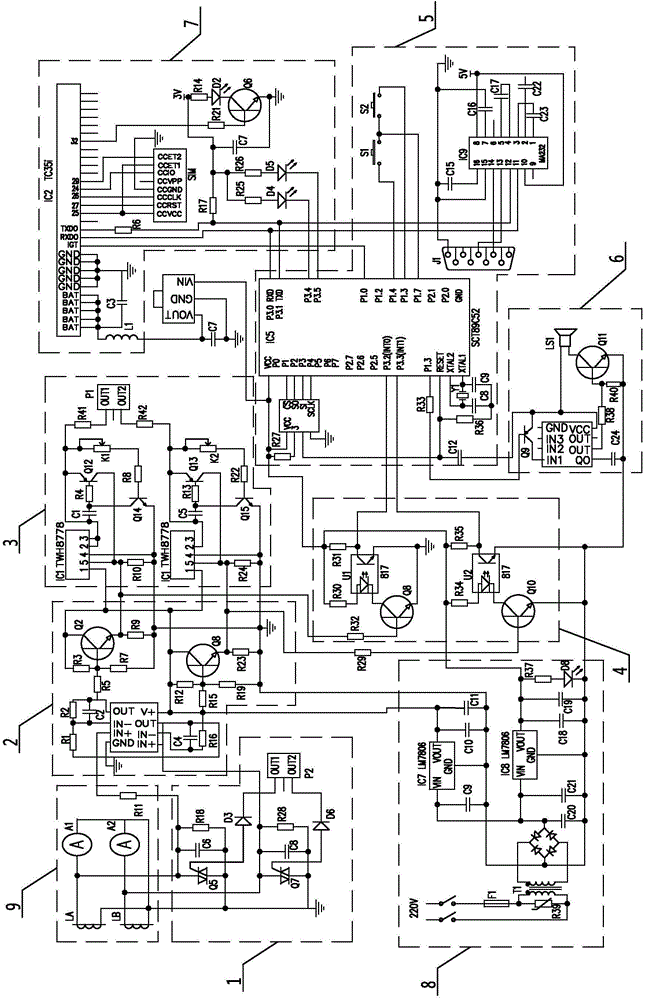
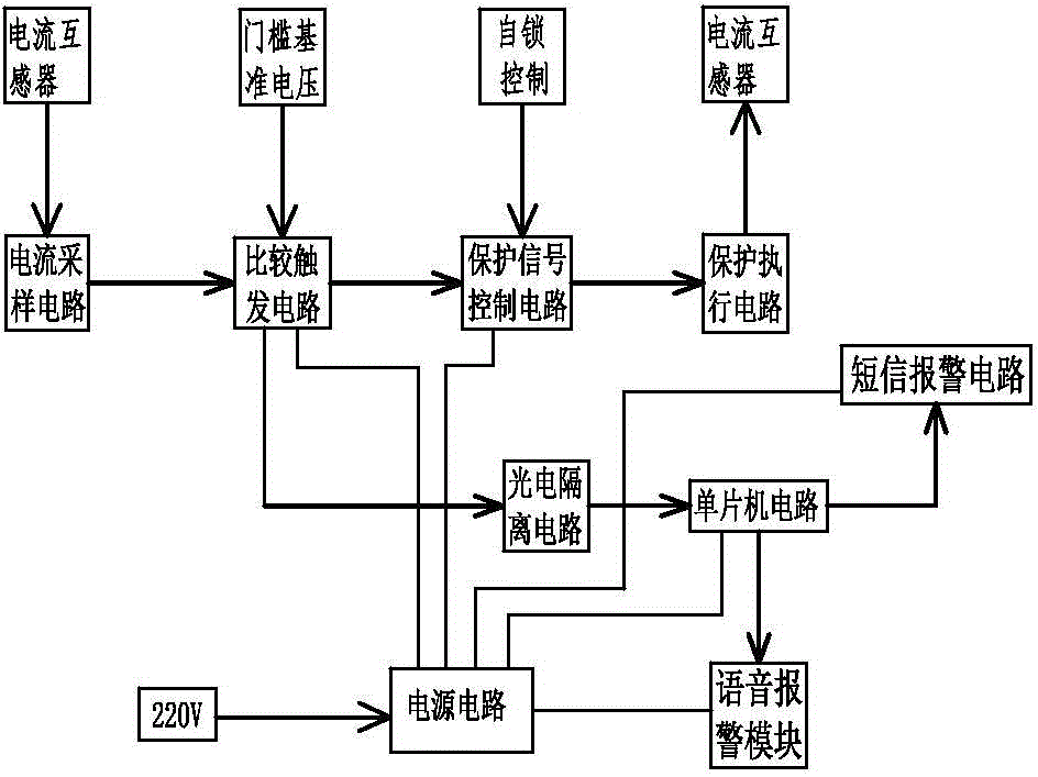
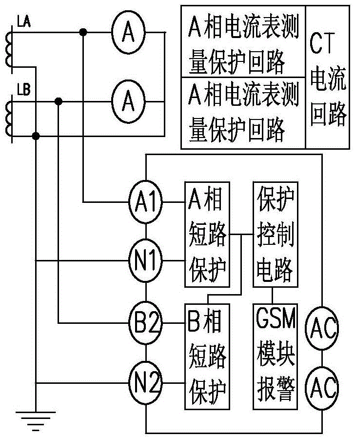
[0030] A current transformer protection device with remote SMS alarm function, including current acquisition circuit 9, protection execution circuit 1, comparison trigger circuit 2, protection signal control circuit 3, photoelectric isolation circuit 4, power supply circuit 8, microcontroller circuit 5, and SMS alarm circuit 7 and voice alarm module 6, current acquisition circuit 9 includes ammeter A1, ammeter A2 and resistance R11, ammeter A1 connects the current transformer LA of A phase, and ammeter A2 connects B phase current transformer LB; Ammeter A1 and ammeter A2 are connected in parallel to resistance R11, resistance R11 is connected to the comparison trigger circuit 2, the comparison trigger circuit 2 is connected to the protection signal control circuit 3, the protection signal control circuit 3 is connected to the protection execution circuit 1, and the pro...


PUM


Abstract

The invention discloses a current transformer protection device with a remote short message alarming function, which comprises a protection execution circuit, a comparison trigger circuit, a protection signal control circuit, a photoelectric isolation circuit, a power supply circuit, a singlechip microcomputer circuit, a short message alarming circuit and a voice alarming module, wherein the protection execution circuit arranged on a current transformer is connected to the comparison trigger circuit and the protection signal control circuit, the comparison trigger circuit is connected to the protection signal control circuit, the comparison trigger circuit is connected to the singlechip microcomputer circuit through the photoelectric isolation circuit, and the singlechip microcomputer circuit is connected to the short message alarming circuit and the voice alarming module; and the power supply circuit is connected to the comparison trigger circuit, the protection signal control circuit, the singlechip microcomputer circuit, the short message alarming circuit and the voice alarming module. The current transformer protection device can carry out short-circuit protection when a circumstance of overcurrent or overvoltage occurs in the current transformer, gives out a voice alarm at the same time, and sends a short message to notify the staff to maintain.

Description

technical field [0001] The invention relates to a protection device for a circuit transformer, in particular to a protection device for sending a short message alarm when the secondary side of an unattended current transformer is abnormal in overvoltage and overcurrent. Background technique [0002] The current transformer is an indispensable component of the power system. It is the substation protector that plays the role of current transformation and electrical isolation. It is used in the differential winding, overcurrent winding, measurement winding, busbar protection winding and Superior metering. With the continuous increase of power system capacity, the shortcomings of current transformer exposure become more and more prominent. The loads connected to the secondary side of the current transformer in operation are instruments or relay current coils, etc., the impedance is very small, and it basically operates in a short-circuit state. The magnetic flux generated by th...

Claims


Application Information

Patent Timeline
Patent Type & Authority Applications(China)
IPC IPC(8): H02H9/00H02J13/00
CPCY02B90/20Y04S40/126
Inventor 张文清张文霞
Owner STATE GRID CORP OF CHINA
Learn More