car charging device
A vehicle charging and circuit technology, applied in circuit devices, battery circuit devices, output power conversion devices, etc., can solve the problems of complex circuit design, high energy loss, and high quality.
- Summary
- Abstract
- Description
- Claims
- Application Information
AI Technical Summary
Problems solved by technology
Method used
Image
Examples
Embodiment 1
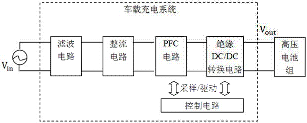
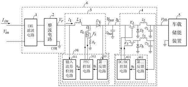
[0036] In this embodiment, a vehicle charging device is provided, such as figure 2 and image 3 As shown, it includes an electromagnetic interference (EMI) filter circuit 1, a rectifier circuit 2, a power factor compensation circuit 3, a DC / DC conversion circuit 4 and a vehicle-mounted energy storage device 5 connected in sequence, and the DC / DC conversion circuit 4 includes a switch circuit, and The DC / DC control circuit 411 connected to the control end of the switch circuit and the second feedback circuit 412 connected to the output end of the switch circuit, the output end of the second feedback circuit 412 is connected to the input end of the DC / DC control circuit 411, and the switch circuit includes a switch K 2 , inductance L 2 and capacitance C 2 , switch K 2 , inductance L 2 After being connected in series as the output terminal of the switch circuit, the capacitor C 2 One end of it is connected to the output end, and the other end is grounded.
[0037] In this...
Embodiment 2
[0055] On the basis of the above-mentioned embodiment 1, the on-board charging device of the embodiment of the present invention adds a current feedback circuit, such as Figure 5 As shown, a current feedback circuit is also included, and the current feedback circuit includes a current detection circuit 413 respectively connected to the output terminal of the DC / DC conversion circuit 4 and the input terminal of the DC / DC control circuit 411 . The current detection circuit 413 is for the current output by the DC / DC conversion circuit 4, that is, for the inductance L 2 or inductance L 3 The output current is sampled, and the sampled signal is input to the DC / DC control circuit 411 . In this way, both the voltage sampling closed-loop circuit: the second feedback circuit 412 and the current closed-loop sampling circuit: the current detection circuit 413 are included in the DC / DC conversion circuit 4. This structure can ensure that the DC / DC conversion circuit 4 can output The st...
PUM
 Abstract
Description
Claims
Application Information
 - R&D
- Intellectual Property
- Life Sciences
- Materials
- Tech Scout
- Unparalleled Data Quality
- Higher Quality Content
- 60% Fewer Hallucinations
Browse by: Latest US Patents, China's latest patents, Technical Efficacy Thesaurus, Application Domain, Technology Topic, Popular Technical Reports.
© 2025 PatSnap. All rights reserved.Legal|Privacy policy|Modern Slavery Act Transparency Statement|Sitemap|About US| Contact US: help@patsnap.com


