A spinal rod system

A nail-rod and spine technology, which is applied in the field of fixation devices in spinal repairs, can solve the problems of destroying the micro-movement of the rod body, weak rigidity, and operation failure, etc.

Active Publication Date: 2017-07-11
BEIJING NATON TECH GRP CO LTD +2
View PDF7 Cites 0 Cited by
  • Summary
  • Abstract
  • Description
  • Claims
  • Application Information

AI Technical Summary

Problems solved by technology

[0003] Most of the currently used spinal dynamic fixation screw-rod systems are realized by the elastic deformation of the fixation rods. For example, the prior art patent document CN100409820 proposes a bioflexible spinal fixation device with shape memory alloy, although the device has better flexibility property, but its rigidity is weak and the stability is poor; the prior art patent document CN101472529 provides a load-bearing elastic spine connection element, the fixing rod is composed of two terminal parts, and a buffer assembly is arranged between the two terminal parts to realize Elastic fixation, but the structure is complicated to process and difficult to realize
And there is a disc-shaped protruding structure extending radially between the two terminal parts of the rod body. Once the screw is fixed, because of the differences between individuals, the screw fixing position is different, and the rod body needs to be bent and shaped to ensure The combination between the rod and the fixing nail conforms to the anatomical structure of the human body, which will destroy the effect of micro-movement of the rod. Moreover, after the fixed rod with irregular structure is locked, it may cause excessive stress concentration at a certain position, and the rod will Fractured, resulting in failed surgery

Method used


Image

  • A spinal rod system
  • A spinal rod system
  • A spinal rod system

Examples


Embodiment Construction

[0029] The spinal rod system of the present invention will be further described in detail through specific embodiments below.

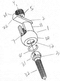
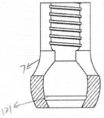
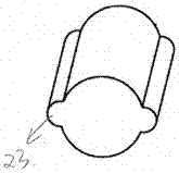
[0030] according to figure 1 . The spinal screw rod system shown in 2 includes a receiving part 1, the upper part of the receiving part 1 is two longitudinally parallel straight arm structures 11, the inner surfaces of the two straight arms 11 are arc surfaces, the proximal end has a threaded structure 111, and the upper outer surface Being a cylindrical structure, a channel is defined between the two parallel arms, which channel defines a longitudinal axis Y. The lower part has an outwardly protruding enlarged structure 12. The enlarged structure 12 can be a symmetrical arc-shaped structure, an asymmetric arc-shaped structure, or an outwardly convex straight column or cone-shaped structure, as long as it can ensure that it can accommodate The accommodating space of the screw head of the elastic structure does not deviate from the spirit of the prese...


PUM


Abstract

The invention provides a spinal screw rod system, including a receiver, a rod, an anchor and a locking screw. The rod passes through the locking member and is locked by the locking screw. Through the unique connection between the receiving member and the anchor The method realizes the stability of the screw-rod system and can also produce a certain amount of micro-motion. This system can effectively improve the fusion rate and long-term stability of spinal products, and it is easy to install, which can reduce surgical operation steps and greatly shorten surgical operation time. .

Description

technical field [0001] The invention relates to the field of orthopedic implants, and further relates to a fixation device in spinal repair. Background technique [0002] Spinal fusion is an important and very useful technique for spinal disorders, whether due to deformity, trauma, segmental instability, or symptomatic disc degeneration. Compared with non-instrument fixation or semi-rigid fixation, the rate of spinal fusion is significantly improved in the rigid spinal fixation formed by the mechanical environment of intersegmental fixation, strong axial screws, and large-diameter longitudinal connecting rod members. However, strong intersegmental fixation also has significant negative effects, including increased stress on adjacent segments, and stress shielding effects affecting bone graft regeneration. Therefore, for painful segments, dynamic fixation is an alternative internal fixation to the current rigid fixation of the spine, which may help to improve the fusion rate...

Claims


Application Information

Patent Timeline
Patent Type & Authority Patents(China)
IPC IPC(8): A61F2/44A61B17/70
Inventor 杨大诚刘云
Owner BEIJING NATON TECH GRP CO LTD
Why Eureka
Try Eureka