
Wiredrawing type high-speed electric arc spraying gun

An arc spraying and wire drawing technology, applied in arc spraying and other directions, can solve the problems of spraying jet divergence, aggravated wear of wire feeding parts, and low particle speed, and achieve spraying jet concentration, high-speed uniform atomization, and atomized particle concentration Effect

Active Publication Date: 2015-09-02
ACADEMY OF ARMORED FORCES ENG PLA +1
View PDF8 Cites 5 Cited by
  • Summary
  • Abstract
  • Description
  • Claims
  • Application Information

AI Technical Summary

Problems solved by technology

[0004] At present, the structure of domestic commercial wire drawing arc spraying gun is relatively simple, and its wire feeding unit basically adjusts the speed and torque of the DC motor to the suitable arc spraying working range through the first-stage planetary gear and worm gear transmission reduction mechanism. , especially the wire feeding driving wheel and wire feeding driven wheel of the wire feeding unit of this arc spraying gun are mostly exposed, and a large amount of dust generated during spraying will seriously pollute the wire surface on the one hand, and then affect the electric transmission parts such as the conductive tip The electrical conductivity of the wire will even affect the quality and performance of the formed coating. On the other hand, it will also aggravate the wear of the wire feeding parts in the wire feeding unit, which will greatly shorten the service life of the arc spray gun.
In addition, at present, most of the atomization units of the spray gun head of the wire drawing arc spray gun use a nozzle structure of primary atomization, which will cause the spray jet to diverge and the particle velocity to be low.

Method used


Image

  • Wiredrawing type high-speed electric arc spraying gun
  • Wiredrawing type high-speed electric arc spraying gun
  • Wiredrawing type high-speed electric arc spraying gun

Examples


Embodiment Construction

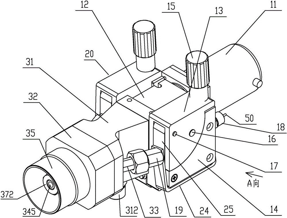
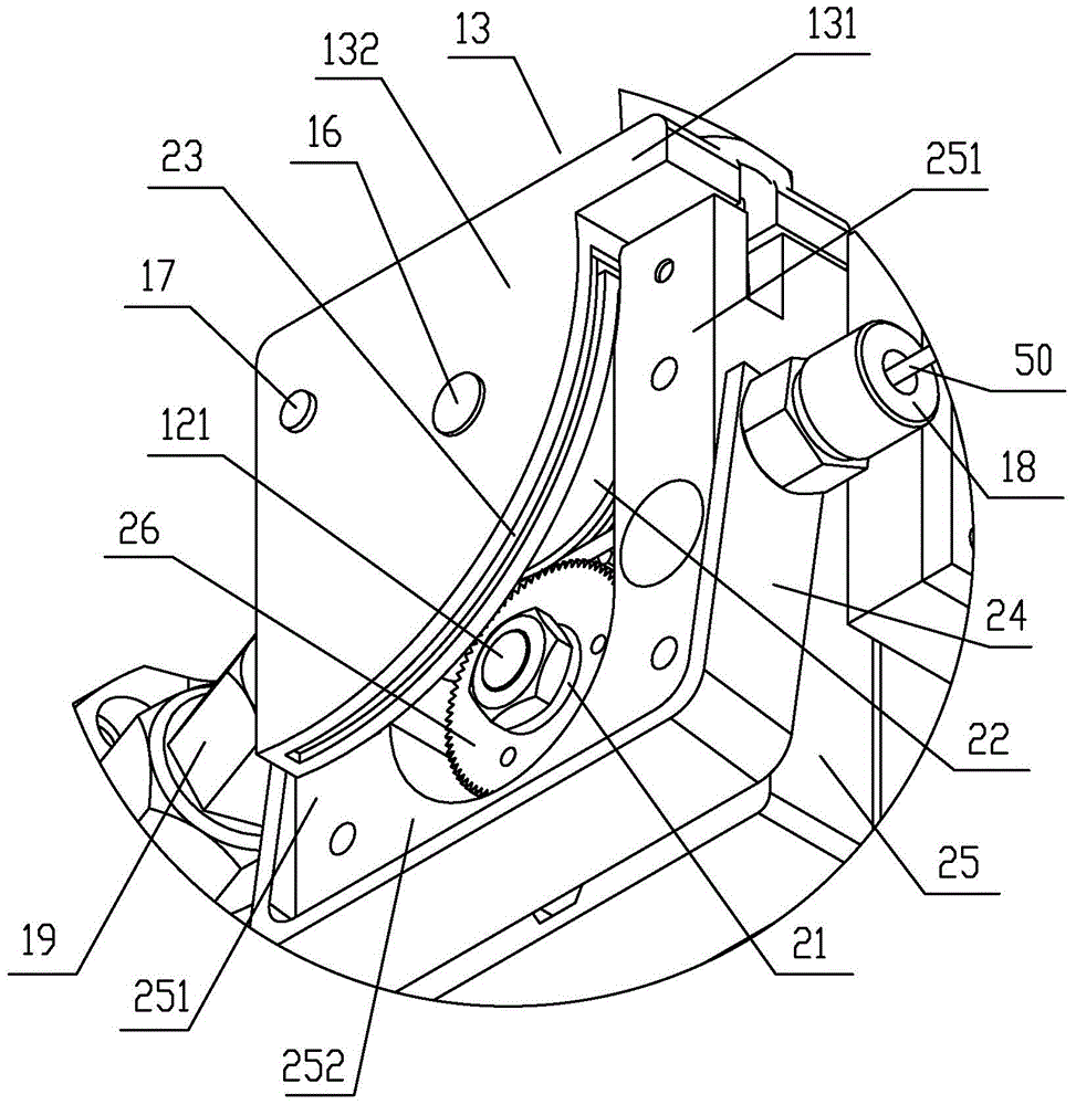
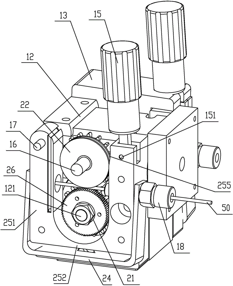
[0025] like Figure 1 to Figure 4 As shown, the wire-drawing high-speed arc spraying gun of the present invention includes a wire-feeding motor 11, a deceleration mechanism 12, a wire-feeding mechanism 20 and a spray gun head 30. 12 at both ends of the output shaft 121 (the output shaft 121 of the reduction mechanism 12 is a double output shaft, and this double output shaft has two output ends, and these two output ends are respectively located on both sides of the reduction mechanism 12) Each is connected to a wire feeding mechanism 20 , that is, the two wire feeding mechanisms 20 are respectively located on both sides of the reduction mechanism 12 and are symmetrically distributed. Specifically, the power of the wire-feeding motor 11 is output to the reduction mechanism 12 through its output shaft, and the reduction mechanism 12 outputs the power to the wire-feeding mechanism 20 through its output shaft 121 after the power is regulated by reducing the speed and increasing th...


PUM


Abstract

The invention discloses a wiredrawing type high-speed electric arc spraying gun. The wiredrawing type high-speed electric arc spraying gun comprises a wire feeding motor, a speed reducing mechanism, wire feeding mechanisms and a spraying gun head, wherein an output shaft of the wire feeding motor is connected with the speed reducing mechanism; two ends of an output shaft of the speed reducing mechanism are connected with the wire feeding mechanisms respectively; wire inlet and outlet pipes are arranged on each wire feeding mechanism; the spraying gun head comprises a rear gun body; a front gun body is mounted at the front end of the rear gun body; a spray nozzle is fixed on the rear gun body through a support seat and extends out of an inner cavity of the front gun body; an airflow flow channel is formed in the rear gun body and penetrates through a converging-diverging flow channel of the spray nozzle; an outer cover is arranged on the outer wall of the spray nozzle, and an annular flow channel communicated with the converging-diverging flow channel is formed between the outer cover and the spray nozzle; the rear gun body is equipped with two current contact nozzles, the current contact nozzles correspond to corresponding wire guiding inclined holes in the spray nozzle, and two wires conveyed from the wire guiding inclined holes are converged nearby the converging-diverging flow channel. According to the wiredrawing type high-speed electric arc spraying gun, the particle spray speed can be increased, so that the atomizing jet is more uniformly concentrated, wire feeding parts in the wire feeding mechanisms are prevented from being contacted with wires and dust, and the service life is effectively prolonged.

Description

technical field [0001] The invention relates to a wire-drawing high-speed electric arc spraying gun, which belongs to the technical field of electric arc spraying. Background technique [0002] As an important branch of thermal spraying, arc spraying technology is widely used to prepare coatings with various properties such as wear resistance and corrosion resistance, so as to realize the dimensional recovery and surface modification of mechanical parts, and even for the field of three-dimensional rapid prototyping of materials . Arc spraying technology originated in the 1920s. It is a spraying process that uses two metal wires to start an arc, melt the wire itself rapidly, and accelerate the molten droplets through high-speed airflow atomization. This arc spraying technology has significant advantages such as high quality, high efficiency, and low cost. For example, the arc spraying efficiency using alloy wire as the spraying material can reach 40kg / h, which is more than 4...

Claims


Application Information

Patent Timeline
Patent Type & Authority Applications(China)
IPC IPC(8): B05B5/06
CPCB05B5/06
Inventor 陈永雄梁秀兵商俊超胡尧强
Owner ACADEMY OF ARMORED FORCES ENG PLA
Learn More