Magnetic sealing device for large-torque magnetic stirrers

A magnetic stirrer and magnetic sealing technology, which is applied in the direction of electromechanical devices, electromechanical transmission devices, and control of mechanical energy, can solve the problems of increasing mechanism difficulty, leakage pollution, leakage, etc., and achieve the solution of sealing failure, leakage pollution, and leakage. Effect

Active Publication Date: 2015-09-02
江苏胜开尔工业技术有限公司
View PDF5 Cites 6 Cited by
  • Summary
  • Abstract
  • Description
  • Claims
  • Application Information

AI Technical Summary

Problems solved by technology

[0003] The mechanical seal cannot be absolutely sealed, and a small amount of leakage pollution is allowed, and there is a limited range of high temperature and high pressure
During operation, the packing seal is easily affected by factors such as wear, corrosion, aging, drying, temperature, etc., and gradually loses its compactness and causes leakage.
Therefore, in the chemical process, various chemical reactions of flammable, explosive, and highly dangerous media under high temperature, high pressure, high vacuum, and high speed, mechanical seals and packing seals are prone to problems such as seal failure and leakage pollution, danger, etc.
[0004] Chinese patent 201420543667.1 discloses a magnetic seal device for a magnetic stirrer, which completely solves the problems of mechanical seals and packing seals that are prone to seal failure and leakage pollution in the past, as well as the problem of lubrication and leakage of the support bearing of the drive shaft in the magnetic seal
However, because the magnetic transmission in this patented technical solution is driven by the rotation of the outer magnetic steel, the inner magnetic steel is driven to rotate, and the inner magnetic steel and the outer magnetic steel are sealed and isolated by a spacer sleeve; when transmitting large torque, a large amount of magnetic steel is required, which increases the cost , and increase the difficulty of the mechanism, so that the magnetic transmission cannot be applied to the high torque transmission

Method used


Image

  • Magnetic sealing device for large-torque magnetic stirrers

Examples


Embodiment Construction

[0021] The present invention will be further described below in conjunction with the accompanying drawings and embodiments.

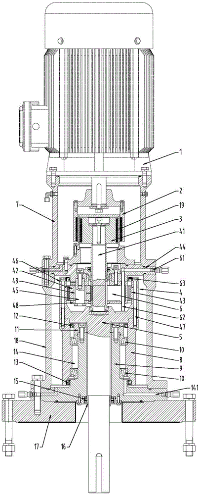
[0022] Such as figure 1 Shown: a magnetic sealing device for a large-torque magnetic stirrer, including a drive motor 1, the output shaft of the drive motor 1 is directly connected to the outer magnetic cylinder 2 of the magnetic coupling, and the magnetic coupling outside the magnetic coupling The inner side of the cylinder 2 is provided with an inner magnetic cylinder 3 of the magnetic coupling corresponding to the outer magnetic cylinder 2 of the magnetic coupling, and an isolation seal is arranged between the outer magnetic cylinder 2 of the magnetic coupling and the inner magnetic cylinder 3 of the magnetic coupling. The sealing cylinder 19, the planetary reducer 4 is located under the inner magnetic cylinder 3 of the magnetic coupling and is fixedly connected to the inner magnetic cylinder 3 of the magnetic coupling through the input sun gear 41 s...


PUM


Abstract

The invention discloses a magnetic sealing device for large-torque magnetic stirrers, comprising a drive motor (1). The output shaft of the drive motor (1) is directly and fixedly connected with a magnetic coupling outer magnetic cylinder (2). A magnetic coupling inner magnetic cylinder (3) corresponding to the magnetic coupling outer magnetic cylinder (2) is arranged at the inner side of the magnetic coupling outer magnetic cylinder (2). The magnetic coupling inner magnetic cylinder (3) is directly and fixedly connected with the top end of an input sun wheel (41) of a planetary reducer (4). The input sun wheel (41) and a planetary wheel (42) are meshed with each other, the other side of the planetary wheel (42) and a gear ring (43) are meshed with each other, and the lower end of the gear ring (43) is fixedly connected with the upper end of an output spindle (5). After the torque of the motor is transferred to the magnetic coupling inner magnetic cylinder under the action of a magnetic field, the speed is reduced through the built-in planetary reducer, and thus large-torque transmission is realized. The consumption of magnetic blocks is low, so that the cost is reduced, and the magnetic vortex heat is small. The magnetic sealing device is suitable for promotion and use.

Description

technical field [0001] The invention relates to the technical field of top-entry chemical mechanical stirring equipment, in particular to a magnetic sealing device for a high-torque magnetic stirrer that reduces costs and realizes high-torque transmission. Background technique [0002] At present, mechanical seals and packing seals are mainly used in chemical mixing applications. The mechanical seal is a shaft seal that relies on a pair or several pairs of end faces perpendicular to the shaft to slide relative to each other, under the action of fluid pressure and the elastic force (or magnetic force) of the compensation mechanism, to keep the moving ring and the static ring in contact and with auxiliary seals to achieve leakage prevention. device. Packing seal means that after the packing is put into the packing cavity, it is compressed axially by the gland screw. When the shaft and the packing move relative to each other, due to the plasticity of the packing, it generates ...

Claims


Application Information

Patent Timeline
Patent Type & Authority Applications(China)
IPC IPC(8): H02K7/10H02K7/116H02K51/00
Inventor 杨胜华柯锦华
Owner 江苏胜开尔工业技术有限公司
Why Eureka
Try Eureka