A circuit floating installation structure

A technology for installing structures and circuits, which is applied in the direction of support structure installation, cooling/ventilation/heating transformation, etc., which can solve the problem of difficulty in ensuring good contact between the radiator and the inner wall of the electronic cabin, difficulty in installing circuit boards, radiators and support structures, and circuit The position of the board and the radiator itself cannot be adjusted, etc., so as to achieve the effect of good thermal environment adaptability, good heat dissipation, and increased gap

Inactive Publication Date: 2018-02-02
CHINA NATIONAL OFFSHORE OIL (CHINA) CO LTD +3
View PDF2 Cites 0 Cited by
  • Summary
  • Abstract
  • Description
  • Claims
  • Application Information

AI Technical Summary

Problems solved by technology

[0004] In the existing circuit installation structure, the circuit board and the radiator are fixed on a support structure, and the positions of the circuit board and the radiator and their mutual positions are not adjustable, so it is difficult to ensure good contact between the radiator and the inner wall of the electronic cabin. It blocks the thermal conduction path of electronic components and cannot meet the thermal design requirements of electronic equipment
[0005] At the same time, because the positions of the circuit board and the radiator and their mutual positions are not adjustable, it is difficult to install the circuit board, radiator and supporting structure during installation, which increases the difficulty of installation.

Method used


Image

  • A circuit floating installation structure
  • A circuit floating installation structure
  • A circuit floating installation structure

Examples


Embodiment Construction

[0030] The technical solutions of the present invention will be further described below in conjunction with the drawings and specific implementations.

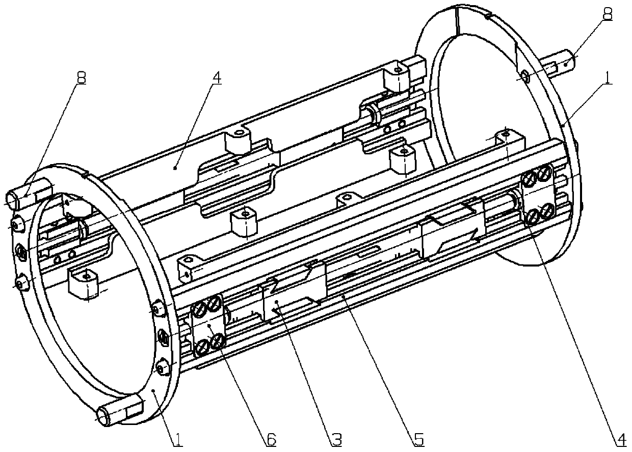
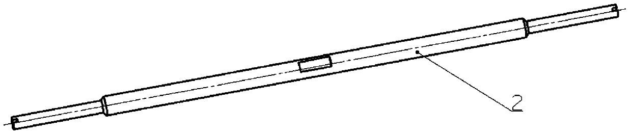
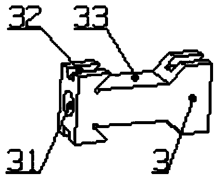
[0031] Such as Figure 1-9 As shown, a circuit floating installation structure includes: a support frame 1, on which at least one set of reverse thread mechanisms that can float up and down are correspondingly installed, and any set of reverse thread mechanisms includes two At least one set of spaced apart circuit boards 10 and a heat sink 20 are installed between the two oppositely mounted reverse screw components, and the heat sink 20 is driven by the reverse screw mechanism When moving to the set height, it abuts against the bulkhead of the electronic cabin where it is located, optimizing the heat conduction path from the electronic components to the inner wall of the electronic cabin.

[0032] The supporting frame 1 is used to connect the reverse screw mechanism to the outside on the one hand, and on the other hand to install t...


PUM


Abstract

The present invention relates to the technical field of heat conduction of electronic equipment, and in particular to a circuit floating installation structure. A circuit floating installation structure includes: a support frame, on which at least one set of reverse thread mechanisms that can float up and down is correspondingly installed, The arbitrary set of reverse thread mechanisms includes two oppositely installed reverse thread assemblies, and at least one set of spaced circuit boards and heat sinks are installed between the two oppositely installed reverse thread assemblies. When the cooling plate moves to a set height under the drive of the reverse screw mechanism, it abuts against the bulkhead of the electronic compartment where it is located. It can semi-automatically and quickly adjust the relative position of the circuit board and the heat sink, promote good contact between the radiator and the inner wall of the electronic compartment, and make the electronic equipment better adaptable to the thermal environment. At the same time, it can increase the distance between the circuit board and the electronic compartment at the beginning of installation. The gap reduces the difficulty of installation, narrows the gap between the circuit board and the electronic compartment, and facilitates heat dissipation.

Description

Technical field [0001] The invention relates to the technical field of thermal conduction of electronic equipment, in particular to a circuit floating mounting structure. Background technique [0002] With the continuous development of electronic assembly technology, the volume of electronic equipment tends to be miniaturized, the system tends to become more complex, and high thermal density has become an irresistible development trend. In order to meet the needs of high heat density, traditional heat dissipation methods such as fans and radiators are constantly being introduced, and new and efficient heat dissipation methods are emerging one after another. [0003] As we all know, the basic methods of internal heat transfer in electronic devices are: heat conduction, convection and thermal radiation. They can appear alone or in two or three forms at the same time. When the heating density of the components exceeds 0.6W / cm2, the lead legs of the components and the components thems...

Claims


Application Information

Patent Timeline
Patent Type & Authority Patents(China)
IPC IPC(8): H05K7/14H05K7/20
Inventor 阎洪涛王建丰王增国李禄祥唐建华李冬翌常炜陈秋华郑莉刘金海崔矿庆
Owner CHINA NATIONAL OFFSHORE OIL (CHINA) CO LTD
Why Eureka
Try Eureka