New type dipping machine

A dipping machine and dipping technology, applied in coatings, devices for coating liquid on the surface, etc., can solve problems such as poor stability and reliability of motion, influence of dipping liquid, and high energy consumption of motion, etc., and achieve compact structure , improve quality and efficiency, and achieve high running stability and reliability

Active Publication Date: 2017-03-01
NINGBO BEILUN LEIAO AUTOMATION EQUIP
View PDF4 Cites 0 Cited by
  • Summary
  • Abstract
  • Description
  • Claims
  • Application Information

AI Technical Summary

Problems solved by technology

[0003] [1] The dipping solution in the dipping tank is prone to agglomeration and affects the fluidity of the dipping solution, thereby affecting the quality and work efficiency of the dipping operation; [2] Outside the outlet box door of the first oven assembly, the second oven The structure of the intermittent support moving mechanism of the hanging rod outside the entrance box door of the component is exactly the same as that of the intermittent support moving mechanism of the hanging rod outside the entrance box door of the first oven assembly, which has an adverse effect on the compactness of the dipping machine ; [3] The support movement mechanism in the hanging rod box has the problems of complex structure, high energy consumption, poor motion stability and reliability, and difficult to accurately control the moving speed of the hanging rod. It has an adverse effect on the performance, which in turn has an adverse effect on the compactness of the structure of the dipping machine

Method used


Image

  • New type dipping machine
  • New type dipping machine
  • New type dipping machine

Examples


Embodiment Construction

[0022] The technical solutions of the present invention will be further specifically described below through the embodiments and in conjunction with the accompanying drawings.

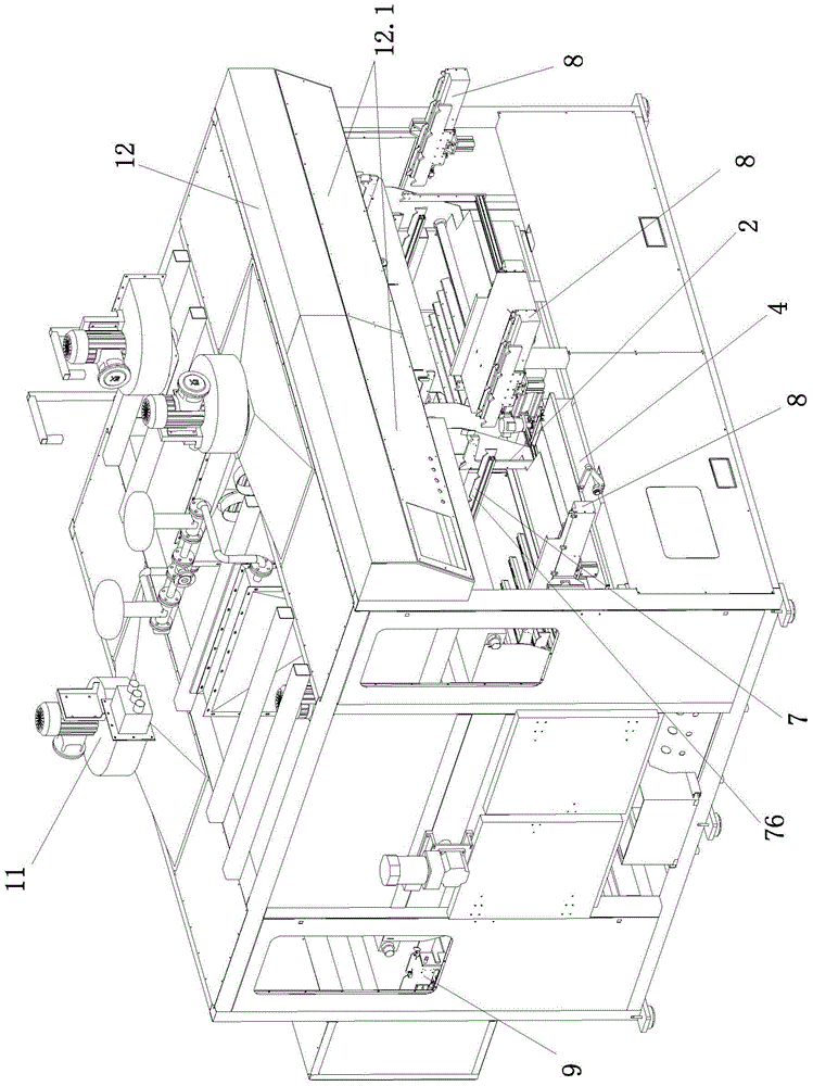
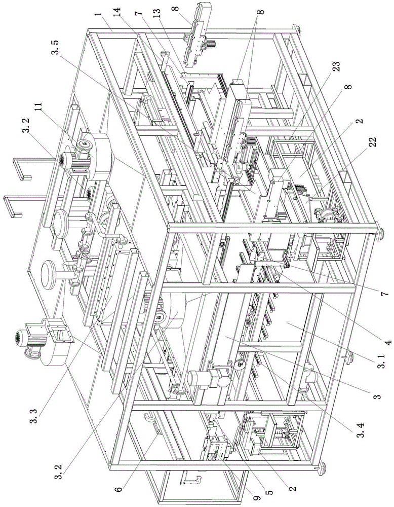
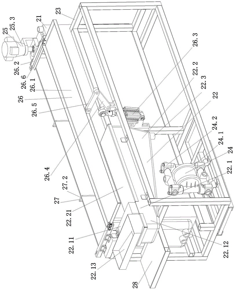
[0023] Such as Figure 1 to Figure 1 1, the present invention includes a frame 1, three dipping tank assemblies 2, first and second oven assemblies 3, front and rear dipping manipulator assemblies 4,5, several workpiece hangers 10 and a control cabinet 12. The workpiece hanging rod 10 is provided with several hanging points for hanging workpieces. The control cabinet includes a PLC [programmable logic controller, not shown in the figure], an input and output unit and an outer cover of the control cabinet, and the output unit includes a display screen and an audible and visual alarm device. The control cabinet is set on the frame in front of the oven body of the two oven assemblies, wherein the control cabinet is provided with two output units 12.1, and the two output units are located at the lower end...


PUM


Abstract

The invention relates to a novel impregnator, which comprises a frame, three glue dipping groove components, a front manipulator manipulator component, a rear manipulator manipulator component, and a workpiece suspension rod; the glue dipping groove component comprises a stirring mechanism, the stirring mechanism comprises a mixer shaft, at least two groups of stirring vanes, and a mixer shaft drive unit; groove bottom of a main body of the glue dipping groove which is close to one end of a circulating pump is lower than one end far from the circulating pump; the mixer shaft is horizontally arranged at one end of the groove bottom of the main body of the glue dipping groove which is far from the circulating pump, each set of stirring vane is fixed on the mixer shaft at intervals, the mixer shaft drive unit is fixed on one end of the glue dipping groove far from the circulating pump, the mixer shaft drive unit is connected with the mixer shaft through transmission, the mixer shaft drive unit is capable of driving mixer shaft to rotate uninterruptedly in 24 hours; a glue storage groove is composed of an overflow groove and a side storage groove which are mutually connected; wherein upper end of the glue storage groove is formed by upper end of the overflow groove, and bottom of the glue storage groove is formed by the bottom of the side storage groove.

Description

technical field [0001] The invention relates to a workpiece surface treatment device, in particular to an improvement on the structure of a dipping machine for dipping the surface of a workpiece before fixing a rubber layer through a vulcanization process to improve the bonding fastness of the rubber layer on the surface of the workpiece. Background technique [0002] In order to make some auto parts have properties such as vibration reduction, noise reduction and buffering, it is often necessary to glue a layer of rubber on the surface of these auto parts through a vulcanization process. In order to improve the adhesive fastness between the rubber layer and the surface of the auto parts, it is often necessary to use a dipping machine to first dip the surface of the auto parts. The application number is 201410267894.0, and the application date is June 16, 2014. The Chinese invention patent application publication named "Dipping Machine and Dipping Process" discloses a dippin...

Claims


Application Information

Patent Timeline
Patent Type & Authority Patents(China)
IPC IPC(8): B05C9/14B05C11/10
Inventor 刘际波
Owner NINGBO BEILUN LEIAO AUTOMATION EQUIP
Why Eureka
Try Eureka