A vacuum suction cup palletizing manipulator

A vacuum suction cup and manipulator technology, applied in the field of palletizing manipulators, can solve problems such as unfavorable continuous production, frequent movements, and increase labor intensity, and achieve the effects of improving surface appearance quality, reducing maintenance workload, and improving overall stability.

Active Publication Date: 2016-08-24
洛阳中冶建材设备有限公司
View PDF7 Cites 0 Cited by
  • Summary
  • Abstract
  • Description
  • Claims
  • Application Information

AI Technical Summary

Problems solved by technology

[0004] Therefore, during the process of being transported into the autoclave (for autoclave curing) and the process of leaving the autoclave after being cured in the autoclave, the adobe N is prone to inclination. , falling into the row gap b, resulting in damage to the bricks, cracking and collapse of the bricks, causing a lot of losses, and moreover, the clips of the palletizing device have to pick up the bricks thousands of times a day, and the movements are frequent. The spacing mechanism is easy to loosen, and the loose clips are easy to scratch the surface of the bricks when they enter the row gap b to clamp bricks and draw out from the row gap b after stacking, resulting in damage to the brick surface, or even damage to the bricks. Affect the appearance quality of adobe and the yield of adobe
In order to prevent the adobe from being damaged, the operator needs to stop the machine every once in a while to adjust the opening distance of the clips. In this way, although the quality of the adobe is guaranteed to a certain extent, the labor intensity of the workers is greatly increased and the production efficiency is reduced. Not conducive to continuous industrial production.

Method used


Image

  • A vacuum suction cup palletizing manipulator
  • A vacuum suction cup palletizing manipulator
  • A vacuum suction cup palletizing manipulator

Examples


Embodiment Construction

[0026] A vacuum suction cup palletizing manipulator comprises a frame 1, and a floating frame 2 is arranged under the frame 1, and the floating frame 2 can float up and down relative to the frame 1, and parallel beams are distributed under the floating frame 2.

[0027] In this embodiment, the floating frame 2 is connected with the frame 1 through the guide rod 16, the upper end of the guide rod 16 is movably connected to the frame 1, and the lower end of the guide rod 16 is fixedly connected with the floating frame 2. The part between the frame 1 and the floating frame 2 is sheathed with a floating spring 17 .

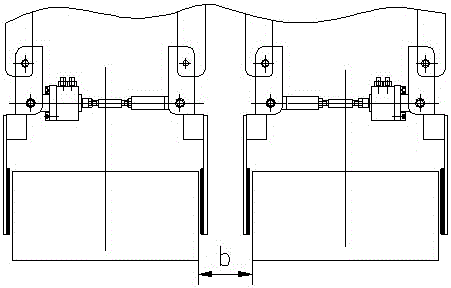
[0028] In this embodiment, there are two beams, one of which is fixedly connected to the floating frame, such as Figure 5 Fixed beam 3 shown. The other beam is connected with the floating frame 2 through the guide rail Ⅱ9 and the slider Ⅱ10, such as Figure 5 In the movable beam 11 shown, the guide rail II9 is ​​fixed on the floating frame 2, the slider II10 is fix...


PUM


Abstract

A vacuum sucker type stacking manipulator comprises a frame, a vacuum generation device and a dust blowing and sweeping mechanism. A floating frame is arranged below the frame, mutually parallel beams are distributed below the floating frame, relative positions between the beams can be changed, a plurality of vacuum sucker components are distributed at the lower ends of the beams, the relative positions of the vacuum sucker components can be changed along the directions of the lengths of the beams, adjacent vacuum sucker components are connected through a limit plate I and a limit screw I, and the vacuum generation device is connected with the vacuum sucker components through pipelines. By the aid of the vacuum sucker type stacking manipulator, the surface appearance quality of a brick blank and overall stability of a brick pillar can be improved, structural stability of the stacking manipulator can be improved, the maintenance workload of the manipulator is reduced, and automation degree of industrial production is finally improved.

Description

technical field [0001] The invention belongs to the technical field of wall material palletizing machinery, in particular to a palletizing manipulator. Background technique [0002] In the production process of autoclaved bricks for wall materials, the brick press usually presses the raw materials in the mold cavity into several rows of adobes at a time, and each row of adobes has several pieces. The shape of the formed brick is as follows: figure 1 As shown, its length, width and height are L, T and H, respectively. The placement of several rows of bricks in the cavity is as follows: figure 2 As shown, there is a block gap a between each adobe in each row, and there is a row gap b between rows of adobes. [0003] In the prior art, these adobes are usually stacked on a maintenance trolley (and then sent to an autoclave for maintenance) by using a clip-type palletizing device. When stacking, the clips of the clip-type palletizing device enter the row gap b to clamp the t...

Claims


Application Information

Patent Timeline
Patent Type & Authority Patents(China)
IPC IPC(8): B25J9/02B25J15/06B65G61/00B08B7/04
Inventor 仝站国安德里亚斯赵栓郭志勇
Owner 洛阳中冶建材设备有限公司
Why Eureka
Try Eureka