High frequency quenching sensor

A technology of high-frequency quenching and induction, which is applied in the direction of quenching device, energy efficiency improvement, process efficiency improvement, etc. It can solve the problem of low work efficiency, inability to realize batch continuous large-scale production, surface hardness hardened layer deviation, etc. problems, to improve production efficiency, realize continuous large-scale production, and ensure uniformity

Active Publication Date: 2016-08-24
CHANGZHOU INST OF MECHATRONIC TECH
View PDF4 Cites 1 Cited by
  • Summary
  • Abstract
  • Description
  • Claims
  • Application Information

AI Technical Summary

Problems solved by technology

At present, in order to ensure the surface hardness and the uniformity of the hardened layer, copying coils or cylindrical inductors are usually used to perform induction quenching heating on individual parts. Low and there will be deviations in surface hardness and hardened layer between one or several groups of parts
The quality of the product is closely related to the operating level of the employees, and it is impossible to achieve continuous large-scale production in batches

Method used


Image

  • High frequency quenching sensor
  • High frequency quenching sensor
  • High frequency quenching sensor

Examples


Embodiment Construction

[0024] In order to make the content of the present invention more clearly understood, the present invention will be further described in detail below based on specific embodiments and in conjunction with the accompanying drawings.

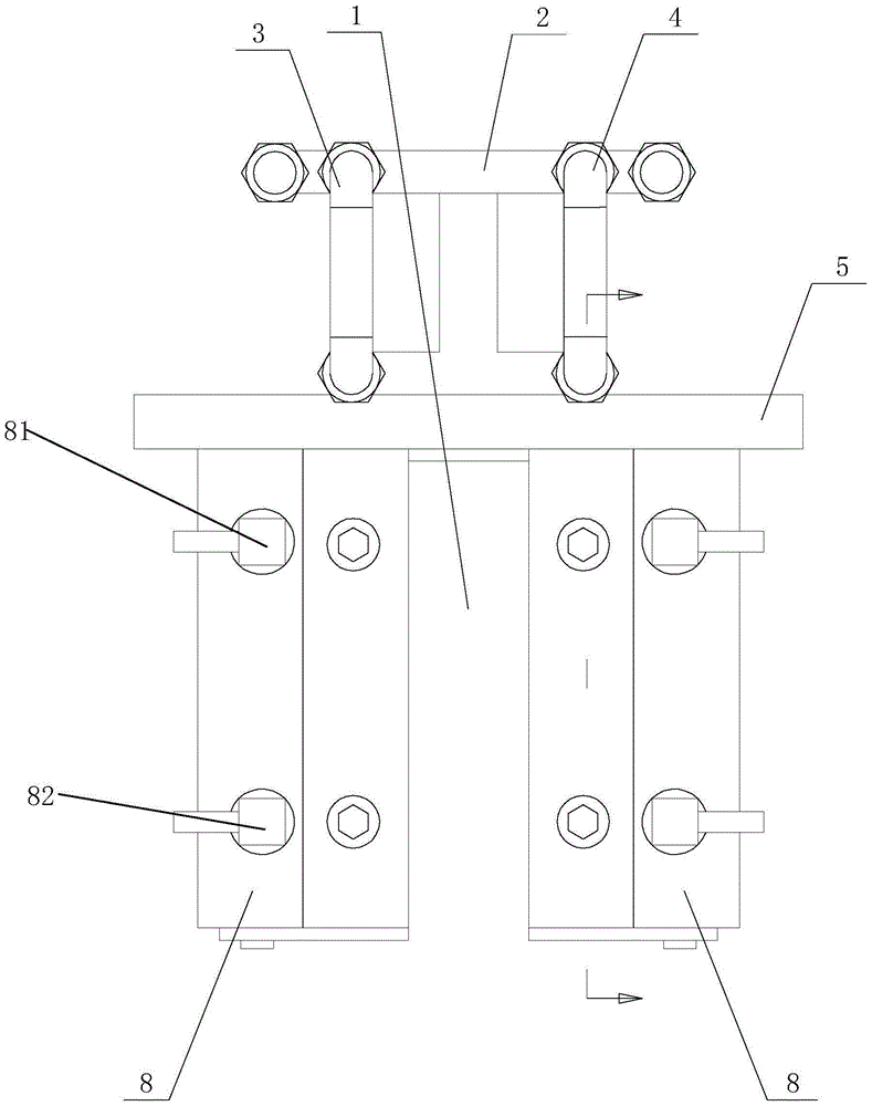
[0025] Such as Figure 1~5 As shown, a high-frequency quenching inductor, which includes:

[0026] Coolant inlet pipe 3;

[0027] Coolant outlet pipe 4;

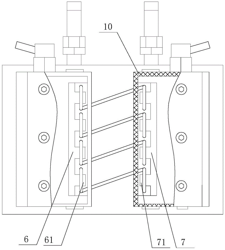
[0028] The first graphite block 6, at least one boss 61 is arranged on the first graphite block 6;

[0029] The second graphite block 7, the second graphite block 7 is provided with at least one matching boss 71, the boss 61 corresponds to the matching boss 71 one by one, and the boss 61 and the matching boss 71 are arranged symmetrically;

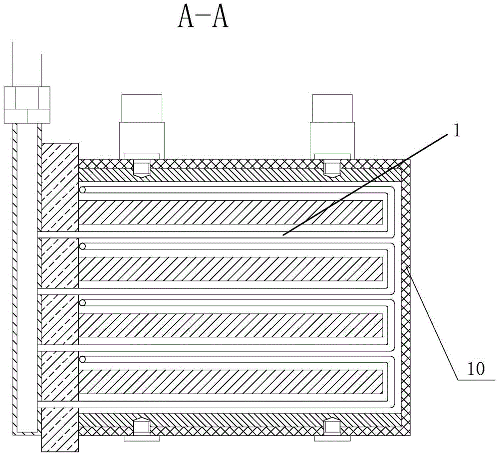
[0030] At least one set of hollow coils 1, the starting end of the hollow coil 1 communicates with the coolant inlet pipe 3, and then extends around the boss 61 to the mating boss 71, and surrounds the mating boss 71 and then connects with the coolant The...


PUM


Abstract

The invention discloses a high-frequency quenching inductor. The high-frequency quenching inductor comprises a cooling liquid inlet pipeline, a cooling liquid outlet pipeline, a first graphite block, a second graphite block and at least one hollow coil. The first graphite block is provided with at least one boss, and the second graphite block is provided with at least one matched boss. The bosses and the matched bosses are in one-to-one correspondence and are arranged symmetrically. The starting ends of the hollow coils are communicated with the cooling liquid inlet pipeline, extend to the matched bosses after winding around the bosses by one circle and are communicated with the cooling liquid outlet pipeline after winding around the matched bosses by one circle. Portions, respectively winding around the bosses and the matched bosses, of the hollow coils are U-shaped. The high-frequency quenching inductor has the advantages that uniformity in induction quenching of components and uniformity in product quality are guaranteed, continuous mass production of heat treatment of small shaft type or spring components is achieved, and production efficiency is improved remarkably.

Description

technical field [0001] The invention relates to a high-frequency quenching inductor, which belongs to the technical field of mechanical equipment. Background technique [0002] At present, in order to meet the surface wear resistance of various small shaft parts and the high stress requirements of spring parts, belt furnace quenching + salt bath tempering can also be used to form a martensitic layer. The method of type furnace + salt bath tempering consumes a lot of energy, and requires special equipment to control the atmosphere in the furnace and isolate the outside air from entering the furnace. Once the air isolation device in the furnace fails, it is often necessary to scrap all the equipment in the furnace. parts to prevent decarburized off-spec parts from flowing to customers. In addition, every time a belt furnace is used to process parts, it is necessary to place 3 to 5 pieces of samples in advance. After the samples pass the test, they can be put into batches of p...

Claims


Application Information

Patent Timeline
Patent Type & Authority Patents(China)
IPC IPC(8): C21D1/10C21D1/62
CPCY02P10/25
Inventor 王峰田宏霞马仕麟
Owner CHANGZHOU INST OF MECHATRONIC TECH
Why Eureka
Try Eureka