
Two freedom degree lorentz force outer rotor spherical surface magnetic bearing

A Lorentz force, outer rotor technology, applied in bearings, bearing components, shafts and bearings, etc., can solve the problems of reduced electromagnetic force accuracy, poor thermal conductivity, small maximum output gyro torque, etc., to improve system reliability, increase Deflection angle, the effect of improving accuracy

Inactive Publication Date: 2015-09-09
BEIJING INSTITUTE OF PETROCHEMICAL TECHNOLOGY +1
View PDF8 Cites 17 Cited by
  • Summary
  • Abstract
  • Description
  • Claims
  • Application Information

AI Technical Summary

Problems solved by technology

The Lorentz force magnetic bearing stator in this scheme is a cylindrical cup-shaped stator, and the magnetic gap is a circular column. The Lorentz force magnetic bearing can only deflect at a small angle, generally 1° to 3°, resulting in Magnetic levitation high torque flywheel output high torque time is short and the maximum output gyro torque is small
Due to the edge effect of the magnetically permeable material, the magnetic field inside the air gap in this scheme is not uniform in the radial direction, which causes the magnetic density acting on the control coil to change when the Lorentz force magnetic bearing deflects, thereby reducing the accuracy of the electromagnetic force
In addition, the Lorentz force cup stator in this solution is a non-metallic material with poor thermal conductivity, which is not easy to dissipate heat, resulting in high temperature of the magnetic bearing during operation, which reduces the reliability and life of the magnetic bearing itself

Method used


Image

  • Two freedom degree lorentz force outer rotor spherical surface magnetic bearing
  • Two freedom degree lorentz force outer rotor spherical surface magnetic bearing
  • Two freedom degree lorentz force outer rotor spherical surface magnetic bearing

Examples


specific Embodiment approach

[0019] The preferred embodiment of the two-degree-of-freedom Lorentz force outer rotor spherical magnetic bearing of the present invention is:

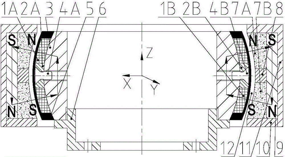
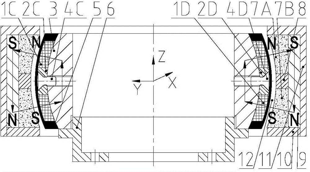
[0020] Mainly composed of two parts: a stator system and a rotor system. The stator system mainly includes: left coil, right coil, front coil, rear coil, left magnetic isolation boss, right magnetic isolation boss, front magnetic isolation boss, rear magnetic isolation convex Table, stator spherical magnetic ring, left magnetic isolation screw, right magnetic isolation screw, front magnetic isolation screw, rear magnetic isolation screw, epoxy resin and mounting seat; the rotor system mainly includes: upper spherical magnetic steel, lower spherical magnetic steel , Magnetic isolation ring, rotor flux-permeable ring, rotor lock nut and rotor sleeve; left coil, right coil, front coil and back coil are used in pairs, left coil and right coil form a pair for radial X-direction deflection control, The front coil and the rear coil form a pair ...

specific Embodiment

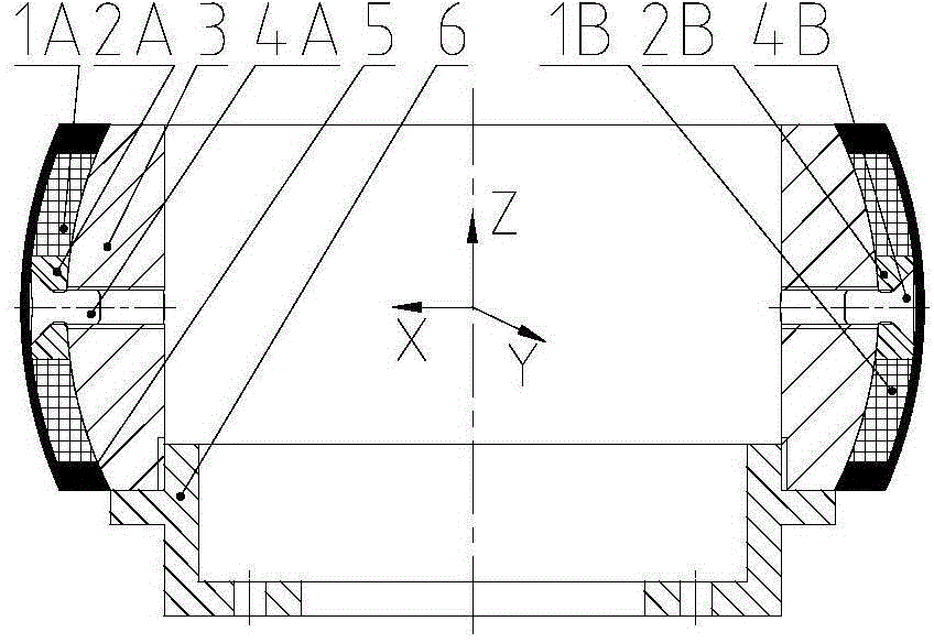
[0031] Such as figure 1 , 2 As shown, a two-degree-of-freedom Lorentz force outer rotor spherical magnetic bearing is mainly composed of a stator system and a rotor system. The stator system mainly includes: left coil 1A, right coil 1B, front coil 1C, rear coil 1D, Left magnetic isolation boss 2A, right magnetic isolation boss 2B, front magnetic isolation boss 2C, rear magnetic isolation boss 2D, stator spherical magnetic ring 3, left magnetic isolation screw 4A, right magnetic isolation screw 4B, front magnetic isolation Screw 4C, rear magnetic isolation screw 4D, epoxy resin 5 and mounting seat 6; the rotor system mainly includes: upper spherical magnet 7A, lower spherical magnet 7B, magnetic isolation ring 8, rotor magnetic ring 9, rotor lock nut 10 and rotor sleeve 11; left coil 1A, right coil 1B, front coil 1C and rear coil 1D are used in pairs, left coil 1A and right coil 1B form a pair for radial X-direction deflection control, front coil 1C and rear Coils 1D form a pair...


PUM


Abstract

The invention discloses a two freedom degree lorentz force outer rotor spherical surface magnetic bearing. The two freedom degree lorentz force outer rotor spherical surface magnetic bearing comprises coils, magnetism isolating convex plates, a stator spherical surface magnetic conductive ring, magnetism isolating screws, epoxy resin glue, an installation pedestal, spherical surface magnetic steels, a magnetism isolating ring, a rotor magnetic conductive ring, a rotor locknut, and a rotor sleeve; the two pairs of coils are used for magnetic bearing radial direction X and Y deflection control respectively, and are fixedly arranged on the stator spherical surface magnetic conductive ring via the epoxy resin glue; the spherical surface magnetic steels are arranged on the radial outer sides of the coils; the inner spherical surfaces of the spherical surface magnetic steels and the outer spherical surface of the rotor magnetic conductive ring are arranged with spherical shell gaps so as to form air gaps. The two freedom degree lorentz force outer rotor spherical surface magnetic bearing is provided with spherical shell gaps, so that the rotor is capable of realizing wide-angle deflection, and a disadvantage of conventional columnar air gap lorentz force of magnetic bearing that, deflection angle is relatively small, is avoided. And in addition, Ampere force generated by current coil current is always tangent to the spherical surface of the coil no matter which position the rotor is deflected to, that is to say, force arm of the force couple composed of the Ampere force of each pair of coils is constant, and lorentz force control moment precision is improved.

Description

Technical field [0001] The invention relates to a non-contact magnetic suspension bearing, in particular to a two-degree-of-freedom Lorentz force outer rotor spherical magnetic bearing. Background technique [0002] Magnetic suspension bearings are divided into reluctance magnetic bearings and Lorentz force magnetic bearings. The former changes the size of the magnetic flux by changing the air gap reluctance of the magnetic bearing, thereby controlling the electromagnetic force output by the magnetic bearing. Since the electromagnetic force is proportional to the square of the magnetic flux, and the magnetic flux is proportional to the magnetomotive force of the coil, the electromagnetic force of the reluctance magnetic bearing has a square relationship with the coil control current, and the linear range after linearization is narrow. The air gap reluctance and magnetomotive force of the Lorentz force magnetic bearing are constant, the magnetic density and flux in the air gap rem...

Claims


Application Information

Patent Timeline
IPC IPC(8): F16C32/04F16C37/00
Inventor 刘强孟伟梁栋航
Owner BEIJING INSTITUTE OF PETROCHEMICAL TECHNOLOGY
Learn More