LED free-form curved face lens used for optical microscope illumination system

An optical microscope and lighting system technology, which is applied to the components of lighting devices, lighting devices, lighting and heating equipment, etc., can solve the problems of unfixed lighting distance, inability to obtain effects, and different LED luminous characteristics

Active Publication Date: 2015-09-09
SOUTH CHINA UNIV OF TECH
View PDF5 Cites 7 Cited by
  • Summary
  • Abstract
  • Description
  • Claims
  • Application Information

AI Technical Summary

Problems solved by technology

However, due to the different luminous characteristics of LEDs from traditional light sources, it is usually not possible to obtain the desired effect when directly applied to the microscope illumination system.
And because the illumination distance of the microscope is usually not fixed, it also brings new obstacles to the application of LED in the microscope.

Method used


Image

  • LED free-form curved face lens used for optical microscope illumination system
  • LED free-form curved face lens used for optical microscope illumination system
  • LED free-form curved face lens used for optical microscope illumination system

Examples


Embodiment Construction

[0074] The present invention will be described in detail below in conjunction with the accompanying drawings and embodiments.

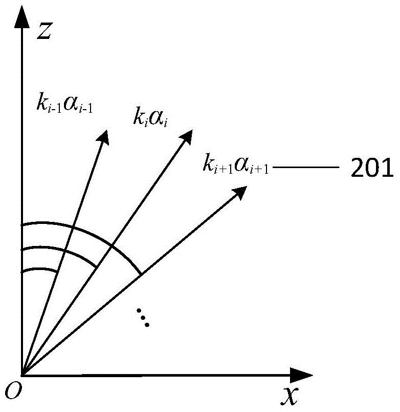
[0075] 1. Set the initial conditions and divide the solid angle of the LED light source.

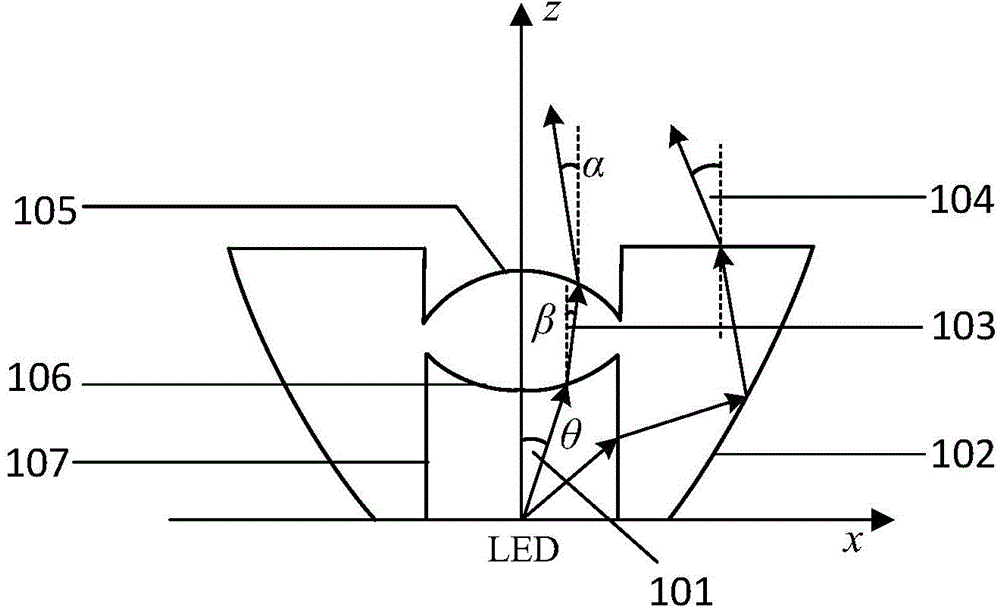
[0076] First, the distance between the target lighting surface and the LED is 200mm, the target lighting area is a circular area, its radius is R=20mm, the total luminous flux of the LED light source is Φ=100lm, and the central light intensity is I 0 =100 / πcd, the average illuminance of the target lighting area is In the coordinate system, θ is the angle between the incident light and the positive direction of the Z axis, and its value range is α is the angle between the outgoing light and the positive direction of the Z axis, and its value range is The refractive index of the lens material is n=1.49386.

[0077] For the free-form surface inside the lens cavity, its main function is to control the exit angle of light. Here set the angle value range of its...


PUM


Abstract

The invention discloses an LED free-form curved face lens used for an optical microscope illumination system. The lens comprises three free-form curved faces. A cavity is formed in the center of the bottom face of the lens, wherein an LED is arranged in the cavity. One part of the cavity wall of the cavity is a cylindrical face which forms an inner side cylindrical face, and the other part of the cavity wall is a free-form curved face which forms an inner side free-form curved face. The inner side free-form curved face is located on the top of the inner side cylindrical face. The inner side free-form curved face and the inner side cylindrical face form an incidence face of the lens. The outer side face of the lens is a free-form curved face which forms an outer side free-form curved face. The middle of the top face of the lens is a free-form curved face which forms a top free-form curved face. The outer side of the top free-form curved face is a partial cylindrical face. The top of the partial cylindrical face is a plane which forms a top plane. A transmitting face of the lens is composed of the top free-form curved face and the top plane of the lens. The LED free-form curved face lens is compact in structure and small in size; the LED free-form curved face lens used for the optical microscope illumination system can form circular light spots which are uniform in illumination distribution on a target illumination face, and meanwhile the high optical efficiency is kept.

Description

technical field [0001] The invention relates to the field of LED lighting, in particular to an LED free-form surface lens used in an optical microscope lighting system. Background technique [0002] Microscope is a precise optical instrument, which has been used in many fields, especially in biology, medicine, experimental teaching and other fields. Its performance is mainly determined by the optical system, such as objective lens, eyepiece, lighting system and so on. In many cases, it is difficult for a well-designed microscope to achieve ideal imaging results. One of the main reasons is that the lighting system is not adjusted to the best state, so that the measured object cannot be well illuminated. [0003] Light sources commonly used in microscope illumination systems include metal halide lamps, arc lamps, and LED light-emitting diodes. The former two are large in size and energy consumption, and do not have excellent monochromaticity. As a new competitive solid-stat...

Claims


Application Information

Patent Timeline
Patent Type & Authority Applications(China)
IPC IPC(8): F21V5/04F21Y101/02
CPCF21V5/046
Inventor 张宪民吴衡李海王恺余金栋
Owner SOUTH CHINA UNIV OF TECH
Why Eureka
Try Eureka