Garbage dual-degradation disposal device

A technology for processing equipment and waste, applied in lighting and heating equipment, combustion methods, combustion types, etc., can solve the problems of low applicability, occupation of large land resources, low waste reduction, etc. Simple, fast, pollution-free, and high reduction in waste disposal

Inactive Publication Date: 2015-09-09
林善祖
View PDF6 Cites 1 Cited by
  • Summary
  • Abstract
  • Description
  • Claims
  • Application Information

AI Technical Summary

Problems solved by technology

This treatment method has the following disadvantages: one, the weight reduction of solid waste is relatively low, generally only reaching about 60% to 70%, that is, the weight of the waste after incineration is still 60% to 70% of that before treatment, and the weight reduction The landfill and other treatment still need to occupy a lot of land resources
The disadvantage of this technology is that it needs external heat supply during operation, and the combustion energy of garbage cannot be fully utilized.
At the same time, the treatment conditions are relatively strict, and different wastes need to be classified and processed before subsequent operations can be carried out. The waste substrates to be treated have high requirements and low applicability
Third, the problem of flue gas generated during the treatment process has not been fundamentally solved, and other treatment equipment is still needed for auxiliary treatment to complete the complete harmless treatment of garbage
[0004] To sum up, although a lot of in-depth research and exploration have been done on the cracking treatment of garbage in the prior art, the existing garbage cracking treatment devices still have complex structures, high manufacturing and operating costs, low waste reduction, and still smoke and dust in the tail gas. Disadvantages such as reprocessing

Method used


Image

  • Garbage dual-degradation disposal device
  • Garbage dual-degradation disposal device

Examples


Embodiment Construction

[0020] The technical concept of the present invention will be further explained below in conjunction with the accompanying drawings and specific embodiments.

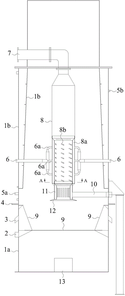
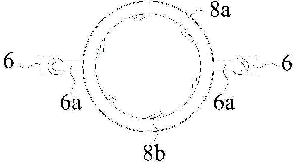
[0021] Such as figure 1 and figure 2 As shown, the garbage double solution treatment device of this embodiment includes an outer furnace body provided with a feed inlet and an inner furnace body 8 placed inside the outer furnace body. The outer furnace body is composed of an upper furnace body 1b and a lower furnace body 1a, and the upper furnace body 1b and the lower furnace body 1a are detachably fixedly connected by a flange 4 . A circulating water channel is opened in the side wall of the upper furnace body 1b, the water inlet 5a of the circulating water channel is located at the lower side wall of the upper furnace body 1b, and the water outlet 5b of the circulating water channel is located at the upper side wall of the upper furnace body 1b. A fire grate 9 is fixedly arranged in the lower furnace body 1a. A gr...


PUM


Abstract

The invention belongs to the field of combustible solid garbage disposal equipment, and particularly provides a garbage dual-degradation disposal device. The garbage dual-degradation disposal device mainly comprises an outer furnace body, an inner furnace body and an oxygen supply device, wherein the inner furnace body is arranged in the outer furnace body, and the oxygen supply device is used for supplying oxygen to the inner furnace body. The garbage dual-degradation disposal device has the advantages that operation of low-temperature cracking and high-temperature combustion can be accomplished in the same device, and garbage disposal is easier, more convenient and rapider; the reduced weight of garbage disposal is large, and is greatly larger than that of the prior art; combustion energy of garbage is sufficiently utilized in the whole garbage disposal process, and more energy is saved; tail gas treatment is easy, convenient and rapid, and free of pollution; the garbage does not need to be selected, and garbage disposal is high in applicability; the device is stable in operation, and smoke combustion is thorough and sufficient; the structure is simple, and disassembly and assembly are convenient; the emergency treatment capacity is high, and automatic and auxiliary ignition operation can be achieved.

Description

technical field [0001] The invention belongs to the field of combustible solid waste treatment equipment, and in particular relates to a double-solution treatment device for waste. Background technique [0002] The traditional solid waste treatment method is direct incineration through an incinerator. This treatment method has the following disadvantages: one, the weight reduction of solid waste is relatively low, generally only reaching about 60% to 70%, that is, the weight of the waste after incineration is still 60% to 70% of that before treatment, and the weight reduction The subsequent landfill and other treatment still need to occupy a large amount of land resources. Second, the garbage after direct incineration will be difficult to degrade due to incomplete incineration. Third, the direct emission of smoke and dust from incineration will still pollute the environment again, requiring secondary purification. [0003] The Chinese invention patent application with the...

Claims


Application Information

Patent Timeline
IPC IPC(8): F23G5/027F23G5/44
CPCF23G5/027F23G5/444
Inventor 林善祖石珍娟严璟丹
Owner 林善祖
Why Eureka
Try Eureka