
Air conditioner indoor unit anti-cold wind control method and system

A technology of air-conditioning indoor unit and control method, which is applied in the directions of air-conditioning system, heating and ventilation control system, space heating and ventilation control input, etc., which can solve the problems of low electrothermal conversion efficiency and achieve improved electrothermal conversion efficiency and measurement accuracy , reducing the effect of misjudgment

Active Publication Date: 2018-03-20
HEFEI HAIER AIR CONDITIONER +2
View PDF8 Cites 1 Cited by
  • Summary
  • Abstract
  • Description
  • Claims
  • Application Information

AI Technical Summary

Problems solved by technology

[0007] In order to solve the problem that the auxiliary heating device installed in the existing indoor heat exchanger heats the air through thermal radiation, and then the heat transfer method of natural convection heat exchange between the air and the heat exchanger is low in electrothermal conversion efficiency, it provides an air-conditioning indoor Machine anti-cold air control method and system, which improves the electrothermal conversion efficiency

Method used


Image

  • Air conditioner indoor unit anti-cold wind control method and system
  • Air conditioner indoor unit anti-cold wind control method and system
  • Air conditioner indoor unit anti-cold wind control method and system

Examples


Embodiment 1

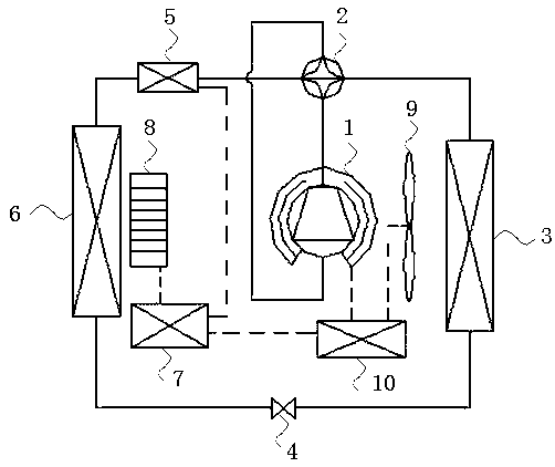
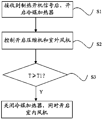
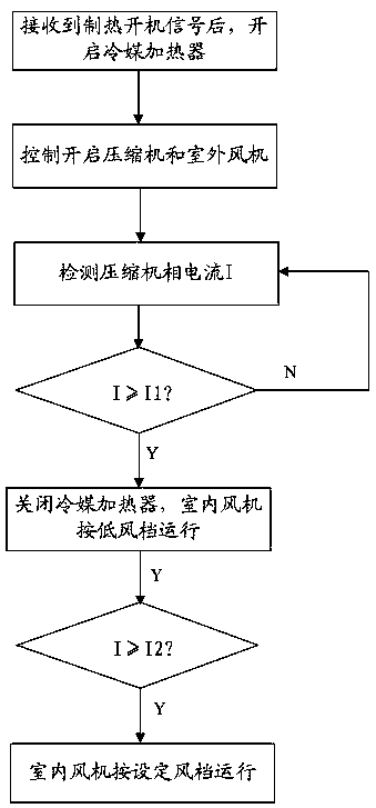
[0037] Embodiment 1. This embodiment provides a method for controlling cold wind of an indoor unit of an air conditioner. In order to clearly illustrate the principle of this method, the structure diagram that may be involved can be found in figure 1 as shown, figure 1 Only one of the air-conditioning systems implementing the method is shown in the figure, including an indoor heat exchanger 6, an indoor fan 8, an indoor controller 7, a compressor 1, an outdoor heat exchanger 3, an outdoor fan 9, and an outdoor controller 10. A refrigerant heater 5 is arranged at the entrance of the indoor heat exchanger 6, which is used to heat the refrigerant in the inlet pipe of the indoor heat exchanger 6. figure 2 As shown, the control method includes the following steps:

[0038] S1. After the indoor controller receives the heating start signal, it turns on the refrigerant heater;

[0039] S2. The outdoor controller controls to turn on the compressor and the outdoor fan;

[0040] S3. ...

Embodiment 2

[0057] Embodiment 2. Based on the cold wind prevention control method for air conditioner indoor units in Embodiment 1, this embodiment provides a cold wind prevention control system for air conditioner indoor units. figure 1 As shown, it includes an indoor heat exchanger 6, an indoor fan 8, an indoor controller 7, a compressor 1, an outdoor heat exchanger 3, an outdoor fan 9, and an outdoor controller 10, and a refrigerant is arranged at the entrance of the indoor heat exchanger 6 The heater 5 is used to heat the refrigerant in the inlet pipeline of the indoor heat exchanger 6;

[0058] The refrigerant heater 5 is controlled by the indoor controller 7, and when the indoor controller 7 receives the heating start signal, it controls to turn on the refrigerant heater 5;

[0059] The outdoor controller 10 is used to control to turn on the compressor 1 and the outdoor fan 9; the steps of the control method can refer to the control method in the first embodiment.

[0060] The indo...


PUM


Abstract

The invention discloses a cold air prevention control method and system of an indoor unit of an air conditioner. The method comprises the steps of: (1) turning on a refrigerant heater after an indoor controller receives a heating starting signal; (2) controlling and turning on a compressor and an outdoor fan by an outdoor controller; and (3) judging if the temperature T of an indoor heat exchanger is higher than a first set temperature T1, if so, controlling and turning off the refrigerant heater, and turning on an indoor fan, wherein the refrigerant heater is used for heating a refrigerant in an inlet pipe of the indoor heat exchanger. The cold air prevention control method of the indoor unit of the air conditioner improves the electricity-heat conversion efficiency through directly heating the refrigerant in the inlet pipe of the indoor heat exchanger.

Description

technical field [0001] The invention belongs to the technical field of air conditioners, and in particular relates to a cold wind prevention control method for an air conditioner indoor unit. Background technique [0002] In the early stage of air conditioner heating, due to the low temperature of the indoor heat exchanger, in order to prevent the air conditioner from blowing cold air, air conditioner manufacturers usually control it by delaying the start of the fan. Faster, the temperature of the indoor heat exchanger will also rise faster. When the temperature of the indoor heat exchanger sensor reaches the set temperature, or the delay time reaches the set value, the fan will be turned on, which is regarded as anti-cold wind control. [0003] In actual use, this control method has the following problems: [0004] 1. When the outdoor environment is lower than 0 degrees and the indoor environment is lower than 20 degrees, after the heating is turned on, the temperature sen...

Claims


Application Information

Patent Timeline
Patent Type & Authority Patents(China)
IPC IPC(8): F24F11/00F24F13/30
CPCF24F11/30F24F11/70F24F11/77F24F2110/00F24F2221/34Y02B30/70
Inventor 姚兴
Owner HEFEI HAIER AIR CONDITIONER
Learn More