
Automatic material cutting and forming method and system thereof

An automatic cutting and forming method technology, which is applied in the field of CNC machine tools, can solve the problems of unfavorable resource saving, high labor intensity of workers, and low cutting efficiency, and achieve the effects of improving typesetting accuracy, realizing automatic cutting, and increasing applicability

Active Publication Date: 2015-09-16
DONGGUAN LEANERP SOFTWARE
View PDF5 Cites 5 Cited by
  • Summary
  • Abstract
  • Description
  • Claims
  • Application Information

AI Technical Summary

Problems solved by technology

Most of this cutting method is purely manual operation, and it is necessary to draw a contour line on the material for each standard sample to determine the cutting position. The line is not rigorous. In order to see the drawn outline, a distance of 3-6mm is often reserved between samples, which is easy to waste about 3-10% of the material, which is not conducive to the saving of resources.

Method used


Image

  • Automatic material cutting and forming method and system thereof
  • Automatic material cutting and forming method and system thereof

Examples


Embodiment 1

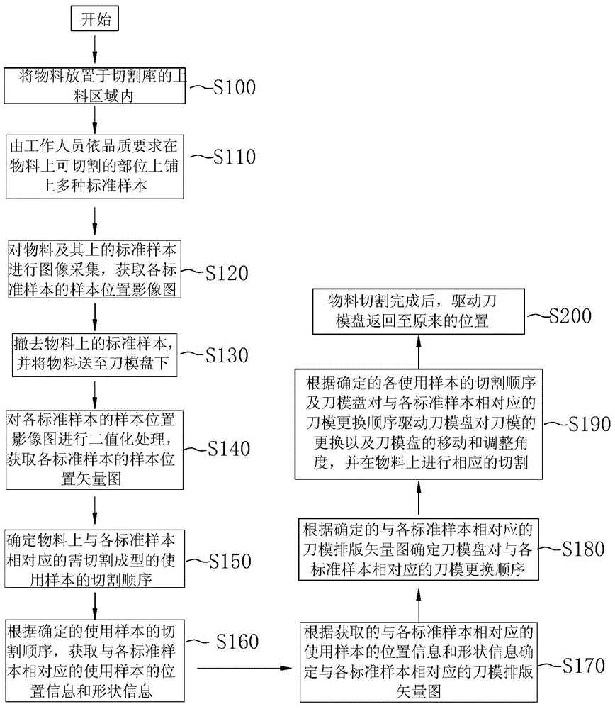
[0049] Please refer to figure 1 , figure 1It is a flow chart of a method for automatic cutting and forming of materials provided in the first embodiment, which includes:

[0050] S100, laying the material flat on the feeding area of ​​the cutting seat;

[0051] Specifically, the material is placed in the feeding area of ​​the cutting seat, and placed flat on the loading plate that can move on the cutting seat, so that the material can be conveniently transported to the die plate.

[0052] In this embodiment, the carrier board is one piece.

[0053] S110. Lay a variety of standard samples on the parts that can be cut by the staff according to the quality requirements;

[0054] Specifically include: the inspection of the material quality by the staff determines the typesetting of the standard sample on the material;

[0055] If the staff inspects the material without damage, the staff will lay multiple standard samples on the entire material, and manually optimize the typese...

Embodiment 2

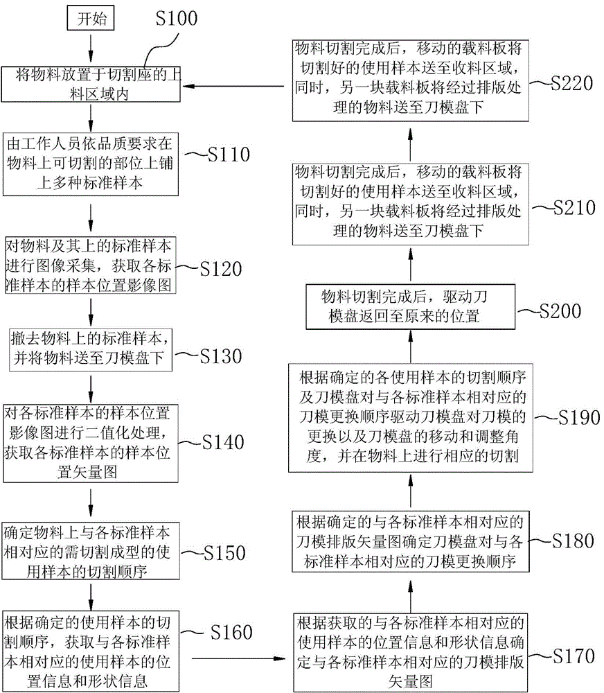
[0074] Please refer to figure 2 , figure 2 It is a flow chart of a method for automatically cutting and forming materials provided in the second embodiment. It differs from the first embodiment in that: there are at least two carrier plates, and at least two carrier plates move circularly on the cutting seat. And after the step S200, it also includes:

[0075] S210. After the cutting of the material is completed, the moving loading plate sends the cut samples to the receiving area, and at the same time, another loading plate transports the typesetting-processed materials to the die tray.

[0076] This step can realize the continuity of material cutting, so that after the material on one loading plate is cut, the other loading plate can carry the material to the die plate, shortening the time between two adjacent material cuttings. The time for exchange under the mold greatly improves the processing efficiency of the entire automatic cutting system.

[0077] S220. The mate...


PUM


Abstract

The invention discloses an automatic material cutting and forming method and a system thereof. The method comprises the steps that materials are flattened and placed in a feeding area of a cutting seat; multiple standard samples are laid on the material portions which can be cut by a worker according to the quality requirements; image acquisition is performed on each standard sample on the materials to acquire a sample position striograph of each standard sample; the standard samples on the materials are removed, and the materials are conveyed to the position under a cutting die plate; a sample position vector diagram, in the DXF, of each standard sample is acquired; the cutting sequence of the using samples needing to be cut and formed on the materials is determined; a cutting die type setting vector diagram is acquired; corresponding cutting is performed on the materials according to the cutting sequence of the using samples and the cutting die type setting vector diagram; after material cutting is finished, the cutting die plate returns to an original position. According to the automatic material cutting and forming method and the system thereof, not only are the optimizing type setting applicability and speedability of the standard samples on the materials with different shapes greatly improved, but also automatic cutting of the materials is achieved, and time and labor are saved.

Description

technical field [0001] The invention relates to the technical field of numerical control machine tools such as stamping and cutting, in particular to an automatic cutting and forming method for materials and a system thereof. Background technique [0002] In the cutting industry, it is often necessary to cut multiple use samples on some materials, such as leather. The traditional use sample cutting process includes the following steps: first spread the material on the cutting seat, and then put the material on the Multiple standard samples, and make a reasonable typesetting of the standard samples, then manually draw the contour line for each standard sample on the material, and finally the operator corresponds to each contour line on the material and its location, holding the corresponding die-cutting tool The corresponding usage samples are produced. Most of this cutting method is purely manual operation, and it is necessary to draw a contour line on the material for each...

Claims


Application Information

Patent Timeline
Patent Type & Authority Applications(China)
IPC IPC(8): B26F1/38B26D7/00
CPCB26D7/00B26F1/38
Inventor 林瑞仁
Owner DONGGUAN LEANERP SOFTWARE
Learn More