

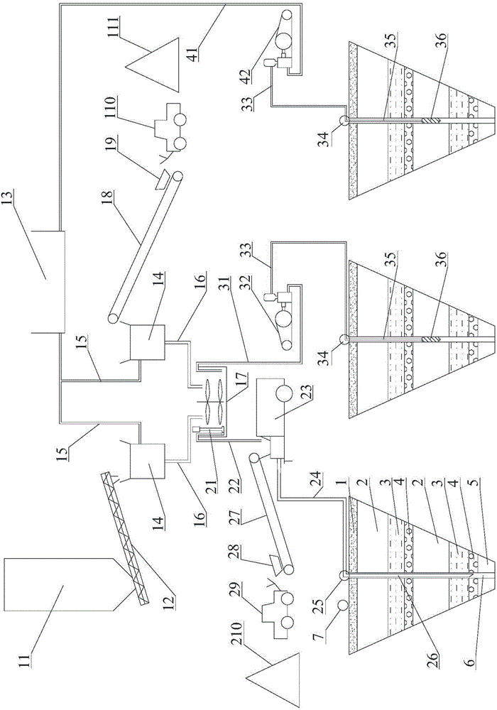
Goaf fast grouting system
A technology of grouting system and goaf, which is applied in mining equipment, earthwork drilling, filling, etc., which can solve the problems of long construction period and high cost, and achieve the effect of large pumping capacity, high pump pressure and shortened construction period
- Summary
- Abstract
- Description
- Claims
- Application Information
AI Technical Summary
Problems solved by technology
Method used
Image

Examples
Embodiment 1
[0052] Only one layer of goaf is distributed within the control area. Before mining, the coal seam is 1.5m thick and the buried depth is 80m. After mining, the height of the caving zone is 8m, and the height of the fracture zone is 15m. rock. In this regard, it was decided to adopt the process of "one-time hole forming and full hole grouting". The specific steps are as follows:
[0053] (1) Construction grouting drilling. It includes three steps: fixed point, installation of drilling rig, and hole formation:
[0054] ① fixed point. Use RTK (real-time dynamic carrier phase difference technology) to stake out on the spot according to the drilling design coordinates, and the error should not exceed 10cm.
[0055] ② Install the drilling rig. According to the position of the lofted hole, the construction platform is leveled, and the down-the-hole hammer drilling rig is in place and installed.
[0056] ③ Hole forming. Use the down-the-hole hammer drilling rig to drill, and use...
Embodiment 2
[0065] There are two layers of gobs distributed within the scope of treatment. The first layer of coal is 1.0m thick and buried 50m deep before mining. After mining, the height of the caving zone is 5m and the height of the fracture zone is 7m. The buried depth is 120m, the height of the caving zone after mining is 8m, and the height of the fissure zone is 15m; the thickness of the Quaternary system here is 10m, and the lower part is all bedrock. In this regard, it was decided to adopt the "one-time hole forming, upward segmental grouting" process, and the specific steps are as follows:
[0066] (1) Construction grouting drilling. It includes three steps: fixed point, installation of drilling rig, and hole formation:
[0067] ① fixed point. Use RTK (real-time dynamic carrier phase difference technology) to stake out on the spot according to the drilling design coordinates, and the error should not exceed 10cm.
[0068] ② Install the drilling rig. According to the position ...
PUM
| Property | Measurement | Unit |
|---|---|---|
| Height | aaaaa | aaaaa |
| Height | aaaaa | aaaaa |
Abstract
Description
Claims
Application Information