Multi-way valve

A technology of multi-way valve and unloading valve, applied in the field of multi-way valve, can solve the problems of disconnection of main engine development, achieve the effect of complete matching, reduce overflow loss and heat generation

Inactive Publication Date: 2015-09-16
JIANGSU KEMAI HYDRAULIC CONTROL SYST
View PDF7 Cites 2 Cited by
  • Summary
  • Abstract
  • Description
  • Claims
  • Application Information

AI Technical Summary

Problems solved by technology

However, the development of the key parts of these main engines - the hydraulic components of the hydraulic system, such as multi-way valves and hydraulic pumps, is seriously out of touch with the development of the main engine, especially high-performance hydraulic components such as high pressure, large flow, and comprehensive functions, and their technology needs to be further improved

Method used


Image

  • Multi-way valve

Examples


Embodiment Construction

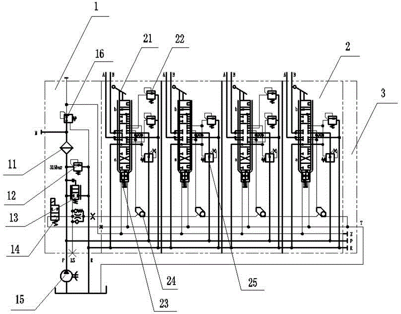
[0016] Such as figure 1 As shown, a multi-way valve includes a connecting block 1, and the connecting block 1 includes a main pressure limiting valve 16, a filter 11, a three-way pressure reducing valve 12, a differential overflow valve 13, an electromagnetic unloading valve 14 and Pump 15, connecting block 1 is connected with reversing block 2, and reversing block 2 includes integral handle seat mechanism 21, secondary pressure limiting valve 22, differential pressure reducing valve 25, shuttle valve 24 and proportional electromagnet 23, said The filter 11 is installed between the main pressure limiting valve 16 and the three-way decompression valve 12, the three-way decompression valve 12 is connected to the differential relief valve 13, the differential relief valve 13 is connected to the pump 15, and the differential relief valve 13 An electromagnetic unloading valve is installed between the valve and the pump, a tail plate is installed behind the reversing block, and a ...


PUM


Abstract

The invention relates to a multi-way valve. The multi-way valve comprises a connecting block, and the connecting block comprises a main pressure limiting valve, a filter, a three-way pressure reduction valve, a constant difference overflow valve, an electromagnetic unloading valve and a pump; and the connecting block is connected with reversing blocks, and the reversing blocks comprise whole handle seat mechanisms, secondary pressure limiting valves, constant difference pressure reduction valves, shuttle valves and ratio electromagnets. Different three-position four-way reversing valves are controlled to achieve single movement and composite movement of a plurality of working devices; according to real-time pressure and the flow magnitude of system loads, the output pressure and the flow magnitude of the hydraulic pump are adjusted, so that the aim that the output power of the pump is completely matched with the loads is achieved; and overflow losses and heating of a hydraulic system are reduced, and therefore energy saving and emission reduction are achieved.

Description

technical field [0001] The invention belongs to the field of design and manufacture of mechanical valves, in particular to a multi-way valve. Background technique [0002] Large-scale, intelligent, high-efficiency and energy-saving are important directions for the development of mainframes in industries such as construction machinery and cranes. Large-scale mainframes put forward higher requirements for their supporting high-pressure and large-flow hydraulic components. Multi-way valves are the core components of the mainframe hydraulic system. Its performance and control method directly affect the performance of the whole machine. However, the development of these key parts of the main engine-hydraulic components of the hydraulic system, such as multi-way valves and hydraulic pumps, is seriously out of touch with the development of the main engine, especially high-performance hydraulic components such as high pressure, large flow, and comprehensive functions, and its tech...

Claims


Application Information

Patent Timeline
IPC IPC(8): F15B13/02
CPCF15B13/02
Inventor 尚增温陈斌张琦
Owner JIANGSU KEMAI HYDRAULIC CONTROL SYST
Why Eureka
Try Eureka