Component quality checking device based on line laser three-dimensional measurement and detection method of device

A quality inspection method and three-dimensional measurement technology, applied to measuring devices, optical devices, instruments, etc., can solve the problems of weak anti-interference, low inspection accuracy, and low efficiency, and achieve good anti-interference and stability, quality The effect of high inspection accuracy and improved detection efficiency

Inactive Publication Date: 2015-09-16
CHANGAN UNIV
View PDF7 Cites 46 Cited by
  • Summary
  • Abstract
  • Description
  • Claims
  • Application Information

AI Technical Summary

Problems solved by technology

In short, the quality inspection is usually carried out by the master worker who selects appropriate measuring tools and determines a reasonable measurement method based on experience. In this way, not only the measurement speed is slow, but also the measurement accuracy cannot be guaranteed.
In addition, for a large number of parts, it is impossible to measure all of them. Only some parts are randomly selected for measurement, and then the quality of the parts in the sample is used to estimate the overall quality. The quality detection effect is poor.
Summarizing the existing methods for detecting auto parts, there are the following deficiencies: 1) The quality inspection of parts requires human intervention, the degree of automation is not high, and the efficiency is low
2) Relying on measuring tools and experience testing by master workers, the uncertain factors are large and the testing accuracy is low
3) Weak anti-interference and unstable measurement

Method used


Image

  • Component quality checking device based on line laser three-dimensional measurement and detection method of device
  • Component quality checking device based on line laser three-dimensional measurement and detection method of device
  • Component quality checking device based on line laser three-dimensional measurement and detection method of device

Examples


Embodiment Construction

[0035] The present invention will be further described in detail below in conjunction with the accompanying drawings.

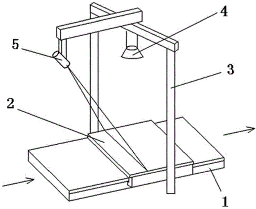
[0036] see figure 1 , the present invention is based on the line laser three-dimensional measurement of the parts quality inspection device, including a laser transmitter 5, a camera 4, a guide rail 1, a mobile platform 2, a bracket 3, a calibration board 6 and a computer;

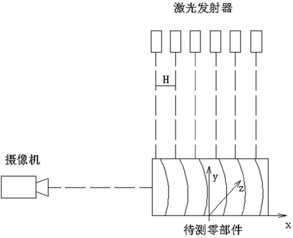
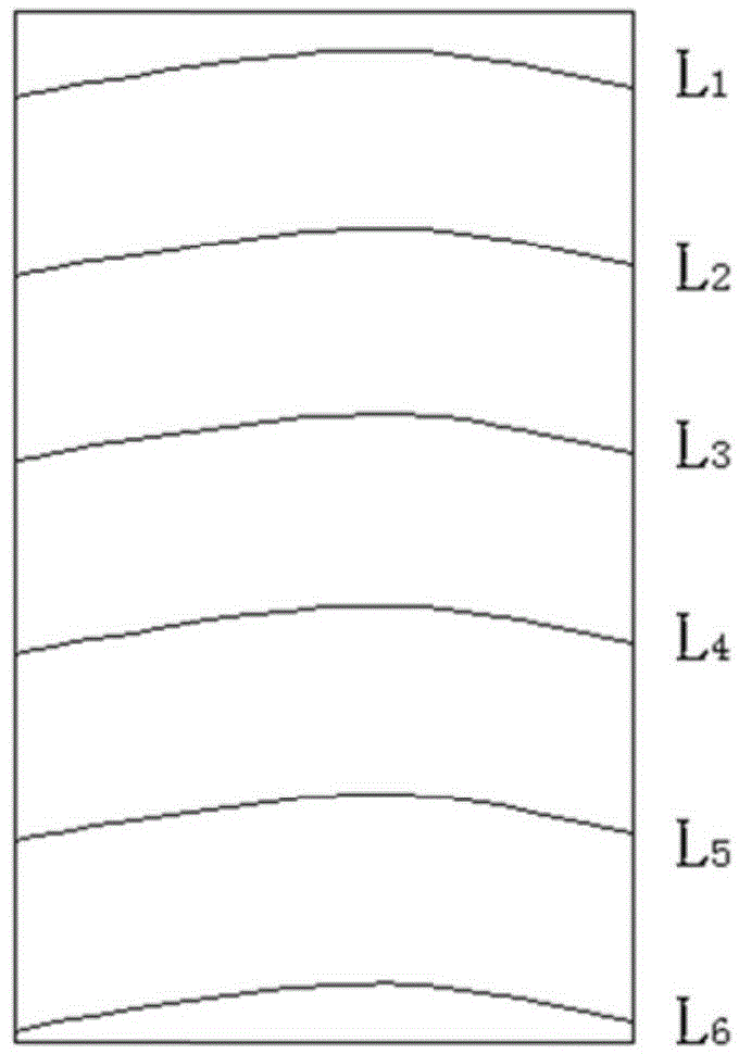
[0037] The laser transmitter 5 adopts six laser transmitters 5 arranged in a straight line, and the distance between two adjacent ones is H, and is used to project six linear stripes with equal spacing H on the component to be tested; the camera 4 is a high-speed CCD camera, which is connected with six The laser emitters 5 are arranged in a collinear arrangement, and are used to collect the images projected by the laser emitters 5 on the surface of the auto parts to be tested and deformed after being modulated by the surface; the computer image signal input end is connected with the image...


PUM


Abstract

The invention provides a component quality checking device based on line laser three-dimensional measurement and detection method of the device. The quality checking device includes a mobile platform mounted on a guide rail and capable of sliding along the guide rail at a uniform speed. To-be-checked components are fixed on the mobile platform. A camera and a plurality of laser emitters are mounted above the guide rail through a mount. The camera collects images which are casted to the surfaces of the to-be-checked components by the laser emitters and deformed due to surface modulation. The camera transmits the collected image data to a computer for analysis and treatment. According to the detection method, by casting linear stripes emitted by the laser emitters to the surface of the to-be-checked components for linear scanning and by utilizing the camera for collecting image information on the to-be-checked components continuously, measured three-dimensional point cloud data and initially designed three-dimensional image are compared and analyzed in the same coordinate system for judging whether the maximum error is within the maximum permissible error range or not and screening out qualified components. The device provided by the invention is high in detection precision and realizes automatic and flow line production.

Description

technical field [0001] The invention belongs to the field of three-dimensional optical measurement and component quality detection, in particular to a component quality inspection device based on line laser three-dimensional measurement and a detection method thereof. Background technique [0002] With the rapid development of the machinery manufacturing industry, many manufacturing industries have put forward higher and higher requirements for the quality control of the parts they process. However, at present, most companies do not do well enough in parts quality inspection due to technology, cost and other issues. In the inspection of parts, one is to use the method of sensory inspection, that is, the inspection personnel only rely on visual, auditory, tactile and other intuitive senses to inspect the technical condition of parts without inspection equipment. This method is simple and low in cost, but this method cannot be used for quantitative inspection, cannot be used ...

Claims


Application Information

Patent Timeline
Patent Type & Authority Applications(China)
IPC IPC(8): G01B11/25
Inventor 刘晶郁杨涎林姚树森张可可焦彬蒙绍夫
Owner CHANGAN UNIV
Why Eureka
Try Eureka