Friction defect detector

A defect detection and display substrate technology, used in material defect testing, TV, instruments, etc., can solve problems such as adverse effects, reduce the utilization rate of production lines, and consume a lot of manpower and material resources, so as to reduce the occurrence of defects and avoid undesired steam injection. uniform effect

Inactive Publication Date: 2015-09-16
HEFEI BOE OPTOELECTRONICS TECH +1
View PDF10 Cites 13 Cited by
  • Summary
  • Abstract
  • Description
  • Claims
  • Application Information

AI Technical Summary

Problems solved by technology

[0007] First, when the water vapor sprayed onto the surface of the glass substrate and the alignment film adheres to the surface of the glass substrate and the alignment film to generate water droplets, due to air flow, evaporation and other factors, the water droplets will continue to disperse, making The detection process requires long-term continuous injection of steam and results in low efficiency
[0008] Second, using manual inspection to detect whether there are defects in the grooves on the alignment film makes the detection efficiency low; moreover, it is difficult to unify the scales of human eye detection by different inspectors, which also makes the reliability of the detection results low.
[0009] Third, because the steam nozzle is held by the inspector, in the case of a large glass substrate and alignment film, some positions of the steam nozzle are "out of reach", which makes it impossible to detect whether there are defects in the grooves in some areas of the alignment film
[0010] Fourth, the steam nozzle is generally directly connected to the heated water tank. When the water level in the water tank is high, some water droplets in the water tank will pass through the steam nozzle and splash onto the alignment film, thereby affecting the subsequent process and causing adverse effects
[0011] Fifth, as the resolution of TFT LCD continues to increase, the grooves on the alignment film are required to be smaller and smaller. Due to the low uniformity of the water droplets produced on the surface of the glass substrate and the alignment film, and the limitations of human observation However, the above-mentioned vapor detection method cannot meet the needs of detection of alignment films in high-resolution TFT LCDs.
[0012] Moreover, since the above-mentioned steam detection method is manual detection, after detection of the groove defect on the alignment film, in general, it is impossible to accurately obtain the position of the defect on the rubbing cloth through manual conversion, which may lead to The repair process cannot eliminate the defects on the friction cloth, so multiple processes are required. If the defects on the friction cloth cannot be eliminated by multiple processes, a new friction cloth must be replaced; thus, it takes a lot of manpower and material resources, and reduces production. utilization rate of the line

Method used


Image

  • Friction defect detector
  • Friction defect detector
  • Friction defect detector

Examples


Embodiment Construction

[0053] The technical solutions in the embodiments of the present invention will be clearly and completely described below in conjunction with the accompanying drawings in the embodiments of the present invention. Obviously, the described embodiments are only a part of the embodiments of the present invention, rather than all the embodiments. Based on the embodiments of the present invention, all other embodiments obtained by those of ordinary skill in the art without creative work shall fall within the protection scope of the present invention.

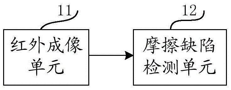
[0054] Such as figure 1 As shown, the friction defect detection device according to the embodiment of the present invention includes:

[0055] The infrared imaging unit 11 is used to perform infrared imaging on the surface of the display substrate provided with the alignment film to obtain an infrared image; and,

[0056] The friction defect detection unit 12 is connected to the infrared imaging unit 11 and is used for detecting whether ther...


PUM


Abstract

The invention provides a friction defect detector. The friction defect detector comprises an infrared imaging unit and a friction defect detecting unit, wherein the infrared imaging unit is used for performing infrared imaging on the surface with an oriented membrane of a display base plate so as to obtain an infrared image; the friction defect detecting unit is used for detecting whether friction defects exist on the orientation membrane according to an infrared radiation brightness temperature distribution diagram of the infrared image. The inactive infrared image of the friction defect is detected by utilizing infrared rays, and compared with steam detection, the inactive infrared image detection is effective so as to prevent unevenness of injected steam.

Description

Technical field [0001] The invention relates to the technical field of friction defect detection, in particular to a friction defect detection device. Background technique [0002] The array substrate and the substrate of the Thin Film Transistor Liquid Crystal Display (hereinafter referred to as TFT LCD) are respectively provided with an alignment film. The alignment film is provided with grooves along a certain direction to make the liquid crystal molecules in the Arrange along the trench direction under the influence of electric field. In general, the polyimide (Polyimide, hereinafter referred to as PI) film coated and cured on the glass substrate is rubbed by the friction cloth wrapped on the friction roller, and the surface of the PI film has a predetermined direction The groove makes the PI film an alignment film with an alignment function. [0003] In the process of preparing the orientation film, due to the possible defects of the friction cloth, such as uneven thickness ...

Claims


Application Information

Patent Timeline
Patent Type & Authority Applications(China)
IPC IPC(8): G01N25/72
CPCG02F1/1309H04N5/33G02F1/133784G02F1/133723H04N23/56
Inventor 井杨坤孙国防陈传辉
Owner HEFEI BOE OPTOELECTRONICS TECH
Why Eureka
Try Eureka