DAC curve-based supersonic wave C scanning imaging method

A scanning imaging and ultrasonic technology, which is applied in the direction of using sound wave/ultrasonic wave/infrasonic wave to analyze solids, etc., can solve the problems of complex image processing process and unintuitive display of equivalent size, achieve wide application prospects, facilitate on-site detection, and improve efficiency.

Inactive Publication Date: 2015-09-16
NANJING UNIV OF SCI & TECH
View PDF4 Cites 11 Cited by
  • Summary
  • Abstract
  • Description
  • Claims
  • Application Information

AI Technical Summary

Problems solved by technology

[0004] The purpose of the present invention is to provide an ultrasonic C-scan imaging method based on the DAC curve to compensate for the influence of factors such as material attenuation and near-field effects on the echo intensity, and to solve the problem of complex image processing after the formation of the ultrasonic C-scan image and the problem of equivalent size display. unintuitive technical issues

Method used


Image

  • DAC curve-based supersonic wave C scanning imaging method
  • DAC curve-based supersonic wave C scanning imaging method
  • DAC curve-based supersonic wave C scanning imaging method

Examples


Embodiment 1

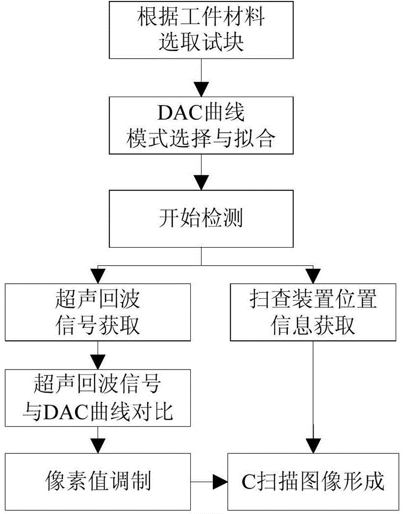
[0028] A kind of ultrasonic C-scan imaging method based on DAC curve, concrete steps are as follows:

[0029] Step 1. Select a test block with the same material as the workpiece to be inspected, and the test block has more than 3 defects with the same aperture and different depths:

[0030] The material of the workpiece to be inspected is aluminum alloy as an example. First, select the test block of aluminum alloy material. The equivalent of the flat-bottomed hole of the test block is 1.2mm, and the flat-bottomed hole is a regular reflector. The flat-bottomed hole has 8 different depths, respectively 2.5mm, 7.5mm, 30mm, 50mm, 70mm, 90mm, 110mm, 120mm.

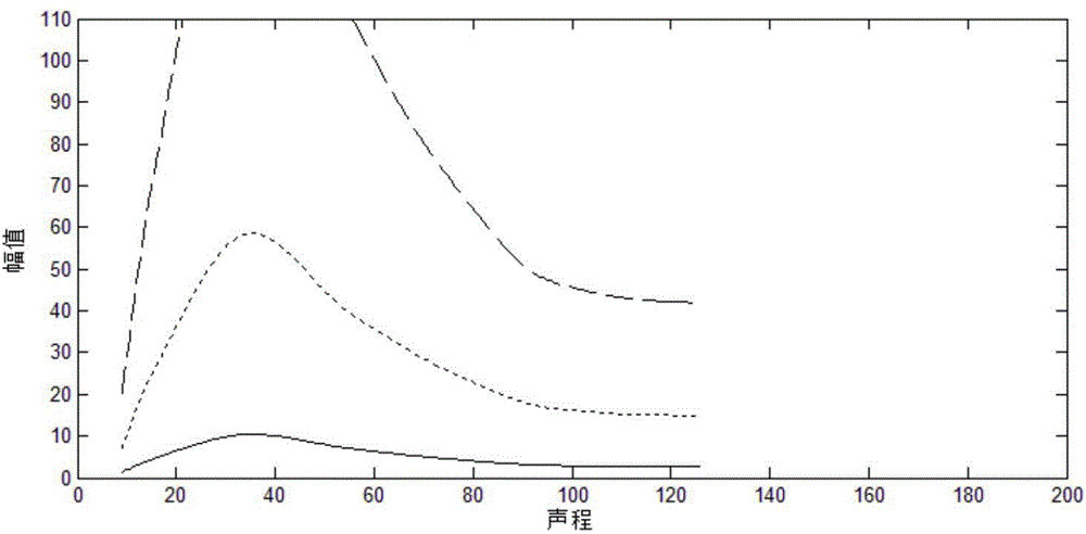
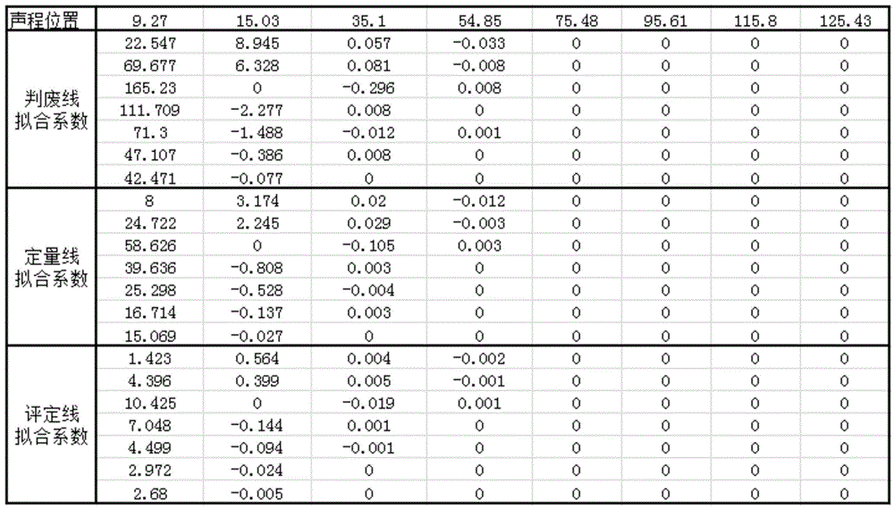
[0031] Step 2. Determine the DAC curve mode and curve fitting method, collect the echo amplitude and sound path data of defects at different depths, and fit the amplitude and sound path data according to the DAC curve mode and curve fitting method selected above to complete the DAC curve:

[0032] There are many types of DAC ...

Embodiment 2

[0047] A kind of ultrasonic C-scan imaging method based on DAC curve, concrete steps are as follows:

[0048] Step 1. Select a test block with the same material as the workpiece to be inspected, and the test block has more than 3 defects with the same aperture and different depths:

[0049] Example 2 of the present invention The material of the inspected workpiece is a magnesium alloy. A test block of the same material is selected. The regular reflector in the test block is a flat-bottomed hole with an equivalent of 1.2mm and 7 different depths, respectively 2.5mm, 7.5mm, and 20mm. , 50mm, 80mm, 90mm, 100mm.

[0050] Step 2. Determine the DAC curve mode and curve fitting method, collect the echo amplitude and sound path data of defects at different depths, and convert the echo amplitude and sound path data of defects at different depths according to the DAC curve mode and curve fitting method selected above Fitting to complete the DAC curve:

[0051] The DAC curve selects th...


PUM


Abstract

The invention discloses a DAC curve-based supersonic wave C scanning imaging method. The method comprises comparing echo height obtained by an ultrasonic flaw detecting system in detection and height at a corresponding sonic path distance position of a fitted DAC curve to obtain dB difference, carrying out color value adjustment according to the difference or a curve zone where the highest echo height exists, and producing a C scanning image by a workpiece position where a flaw detecting system scanning device exists. The method utilizes a DAC curve, prevents influence caused by compensation material attenuation, near field effect, acoustic velocity scattering and surface roughness, is free of later C scanning image edge detection and segmentation in quantitative analysis, realizes visual determination of workpiece defect equivalent sizes or ranges according to color design in C scanning image adjustment, is free of pixel statistics in defect analysis and reduces detection result processing complexity.

Description

technical field [0001] The invention belongs to the field of ultrasonic nondestructive testing, and relates to an ultrasonic C-scan imaging method based on a DAC curve. Background technique [0002] Ultrasonic C-scan imaging method is based on the modulation and imaging of cross-sectional echo information perpendicular to the propagation direction of the sound beam within the ultrasonic detection range during workpiece detection. This method can visually display the position and size of the defect, and then can qualitatively and quantitative analysis. However, the traditional C-scan imaging method, such as an automatic ultrasonic C-scan detection system for ring forgings proposed in Chinese Patent Application No. 201410305302. The impact of the echo intensity between the probes is considered, and the defect detection results need to analyze and process the C-scan image to obtain the defect area and determine whether the workpiece is qualified. The actual operation is compli...

Claims


Application Information

Patent Timeline
Patent Type & Authority Applications(China)
IPC IPC(8): G01N29/06
Inventor 卜雄洙侯亚宾许有昌王新征张振宛静耿永健严曙孟哲
Owner NANJING UNIV OF SCI & TECH
Why Eureka
Try Eureka