Battery component disconnection control system, battery component and vehicle having same

A technology for control systems and battery components, applied in the field of vehicles, can solve problems such as time-consuming and economical costs, increased costs, and long response times, and achieve the effect of reducing maintenance time and economical costs and ensuring work safety.

Active Publication Date: 2017-10-24
QOROS
View PDF5 Cites 0 Cited by
  • Summary
  • Abstract
  • Description
  • Claims
  • Application Information

AI Technical Summary

Problems solved by technology

This method requires a long response time, which is not conducive to circuit safety. At least there are the following problems: first, using the heat of overcurrent current to blow the fuse will cause unnecessary loss of battery energy; second, the fuse in the fuse device depends on the material , Specifications are different, and their aging degrees are also different. Therefore, it is necessary to choose fuses of different materials and specifications according to different service years when selecting. Fuses that perform beyond necessary specifications, resulting in increased cost
In the prior art, there are also a variety of sensing units (such as airbag impact sensors, humidity sensors, impact sensors, etc.) connected with the battery control unit signal. These sensing units can obtain corresponding disconnection signals and then control the fuse through the battery control unit. In this way, the disconnection of the current path of the battery pack is overly dependent on the detection function of the sensor, and in some unavoidable situations, the sensor may fail or work in an abnormal state. Ensure the normal operation of the battery pack disconnection control function, which in turn leads to the risk of damage to the car; in addition, the replacement of the safety device used to cut off the high-voltage circuit in the prior art is also relatively complicated, which takes a lot of time and economic costs

Method used


Image

  • Battery component disconnection control system, battery component and vehicle having same
  • Battery component disconnection control system, battery component and vehicle having same
  • Battery component disconnection control system, battery component and vehicle having same

Examples


Embodiment Construction

[0040] The present invention will be described in detail below in conjunction with specific embodiments shown in the accompanying drawings. However, these embodiments do not limit the present invention, and any structural, method, or functional changes made by those skilled in the art according to these embodiments are included in the protection scope of the present invention.

[0041] The "first" and "second" mentioned in the following embodiments do not represent an absolute distinction in structure or function, but are only for the convenience of description.

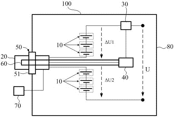
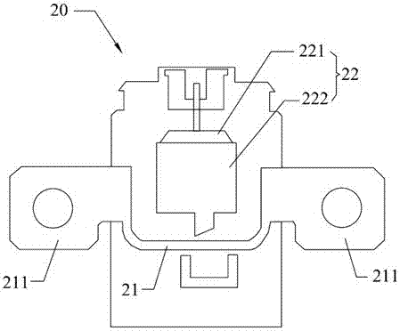
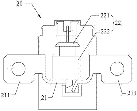
[0042] ginseng figure 1 , to introduce the first specific embodiment of the present invention applied to the disconnection control system of the battery assembly 100 . In this embodiment, the disconnect control system includes a disconnect switch 20 , a circuit information sensor 30 , a disconnect control module 40 and a manual circuit breaker 50 .

[0043]The battery assembly 100 includes a plurality of battery ce...


PUM


Abstract

The invention discloses a battery assembly disconnection control system and a battery assembly and a vehicle thereof. The battery assembly includes a plurality of battery units connected in series, and the disconnection control system includes a manual circuit breaker detachably installed between the battery units in series, A disconnect switch arranged between the battery units, a circuit information sensor arranged in the battery assembly, and a disconnect control module connected with the disconnect switch and the circuit information sensor. The disconnect switch is integrated in the manual circuit breaker and can be triggered by the manual circuit breaker to break the circuit and / or remove from between the battery cells in series. The circuit information sensor is used to detect circuit information and transmit the circuit information to the circuit breaker control module, and the circuit breaker control module is used to generate a first circuit breaker control signal when the circuit information meets a preset fault judgment condition, and the circuit breaker switch is also configured to receive the first circuit breaker It is disconnected when the control signal is disconnected.

Description

technical field [0001] The invention belongs to the technical field of automobile manufacturing, and in particular relates to a circuit breaker control system applied to a battery assembly, a battery assembly with the circuit breaker control system, and a vehicle using the battery assembly. Background technique [0002] High-voltage systems are key safety devices in automotive applications. In hybrid or electric vehicles, for example, how to ensure that high-voltage power sources (such as inverters or the battery of the engine) can be cut off safely and reliably when high-voltage devices suffer faults extremely important. [0003] A commonly used safety device for cutting off high-voltage circuits is a fuse device. The basic principle of the fuse device is to use the heat generated by the overcurrent of the faulty circuit to blow the fuse in the device to disconnect the circuit. This method requires a long response time, which is not conducive to circuit safety. At least th...

Claims


Application Information

Patent Timeline
Patent Type & Authority Patents(China)
IPC IPC(8): H02J7/00
Inventor 狄彼德彦斯·贝肯丁力·罗伯特
Owner QOROS
Why Eureka
Try Eureka