Permanent magnet compound motor

A composite motor and permanent magnet technology, applied in electrical components, electromechanical devices, electric components and other directions, can solve the problems of large amount of permanent magnets, difficult design and manufacturing, complex magnetic field distribution, etc., and achieve low manufacturing costs, simple processing and assembly. The effect of easy operation and high operational reliability

Inactive Publication Date: 2015-09-16
DALIAN JIAOTONG UNIVERSITY
View PDF7 Cites 10 Cited by
  • Summary
  • Abstract
  • Description
  • Claims
  • Application Information

AI Technical Summary

Problems solved by technology

[0004] Existing composite motors have many forms, but no matter what form, its mechanical structure is three layers of permanent magnets and thus forms three layers of air gap; its common disadvantages are: (1)

Method used


Image

  • Permanent magnet compound motor
  • Permanent magnet compound motor
  • Permanent magnet compound motor

Examples


Example Embodiment

[0066] The present invention will be further described below in conjunction with the drawings.

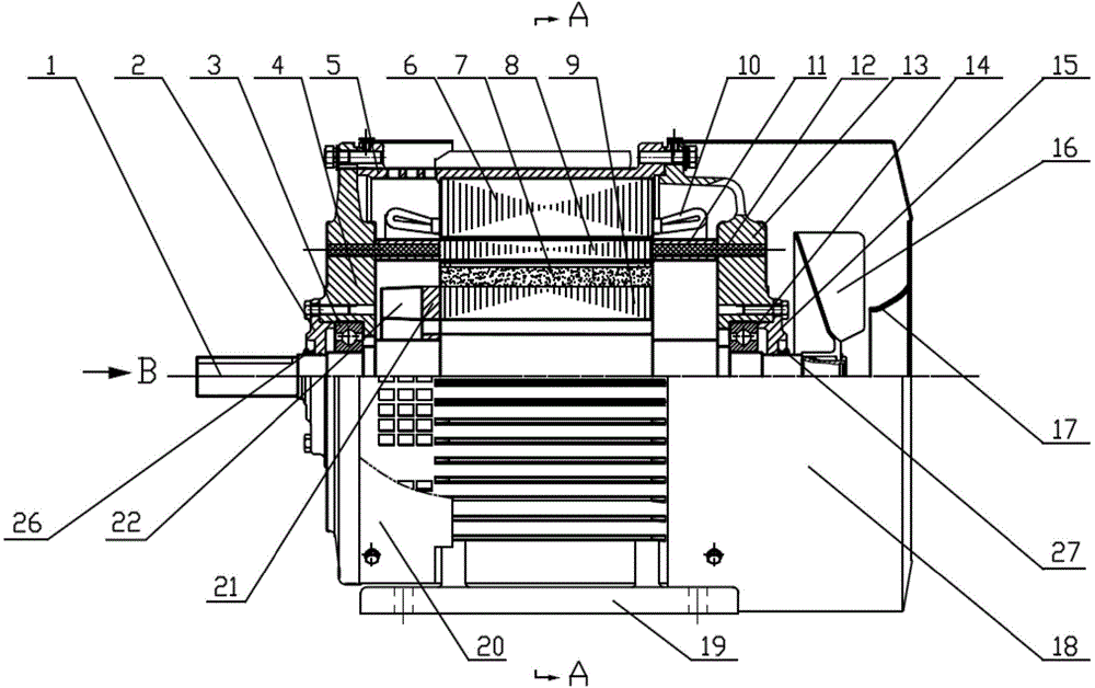
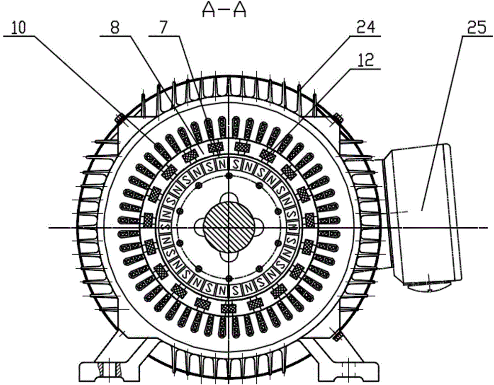
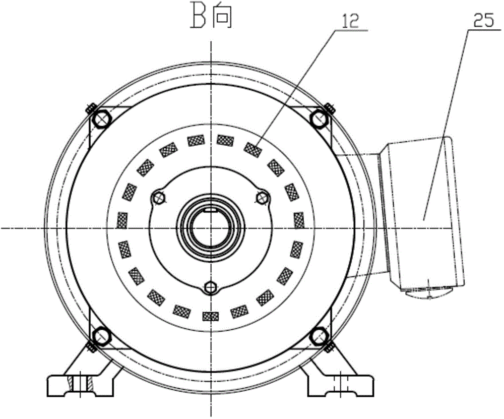
[0067] Such as Figure 1-8 As shown, a permanent magnet composite motor includes a stator assembly, a field-tuning ring assembly, a rotor assembly and a casing assembly.

[0068] The stator assembly includes a stator core 6 and a stator winding 10; the stator core 6 is made of laminated silicon steel sheets insulated on both sides, and the stator core 6 has uniformly distributed slots with the same shape, and the structure is the same as the asynchronous motor stator; The stator winding 10 is a three-phase winding embedded in the 6 slots of the stator core. The structure of the three-phase winding is the same as that of an asynchronous motor. When the stator winding 10 is energized with three-phase alternating current, a rotating magnetic field will be generated.

[0069] The stator core 6 and the casing 5 in the casing assembly are fixed in the same manner as the asynchronous motor.

[0...


PUM


Abstract

The invention discloses a permanent magnet compound motor including a stator assembly, a flux adjusting ring assembly, a rotor assembly and a housing assembly, A uniform air gap layer exists between the stator assembly and the flux adjusting ring assembly. A uniform air gap layer also exists between the flux adjusting ring assembly and the rotor assembly. The permanent magnet compound motor has only one layer of permanent magnets, so that the permanent magnet amount can be saved. The permanent magnet compound motor has only two air gap layers, so that product formation, processing and assembly are all easier and more practical than those in the prior art. The permanent magnet compound motor has only one motion component, so that the permanent magnet compound motor is not easy to get damaged. The permanent magnet compound motor is simple in mechanical structure, low in manufacture cost and high in operation reliability. The permanent magnet is fixed with a built-in mold hole in a rotor core, so that the magnet may not be thrown out due to centrifugal force generated in high speed rotation of the rotor core. Therefore, the permanent magnet compound motor is safe and reliable. The rotor core is equipped with a damping bar made of conductor material, so that rapid convergence of rotation speed and torque can be realized and stable operation can be achieved after the rotor is started. The permanent magnet compound motor is low in heat generation and high in efficiency.

Description

technical field [0001] The invention relates to a permanent magnet composite motor, in particular to a permanent magnet composite motor integrating a permanent magnet gear and a permanent magnet motor. Background technique [0002] Modern drive systems have always tended to direct drive with variable speed, which can save the mechanical gear transmission system, eliminate the vibration and noise caused by mechanical gears, reduce mechanical losses, obtain higher system efficiency, and save energy. [0003] Existing composite motors integrate concentric magnetic gears and permanent magnet synchronous motors so that they can be both speed-adjustable and variable-speed. [0004] Existing composite motors have many forms, but no matter what form, its mechanical structure is three layers of permanent magnets and thus forms three layers of air gap; its common disadvantages are: (1) the amount of permanent magnets is large; (2) The magnetic fields between the three air gaps are co...

Claims


Application Information

Patent Timeline
IPC IPC(8): H02K7/116H02K1/16H02K1/27H02K7/00H02K5/04H02K5/10
Inventor 葛研军王鹏杨均悦周凯凯牛志袁直王彪
Owner DALIAN JIAOTONG UNIVERSITY
Why Eureka
Try Eureka