

Flexible solar cell module
A solar cell and flexible technology, applied in the field of solar cells, can solve the problems of restricting popularization and use, high power consumption and high cost of light tracking components, and achieve the effect of facilitating popularization and use, low cost and high work efficiency
- Summary
- Abstract
- Description
- Claims
- Application Information
AI Technical Summary
Problems solved by technology
Method used
Image

Examples
Embodiment 1
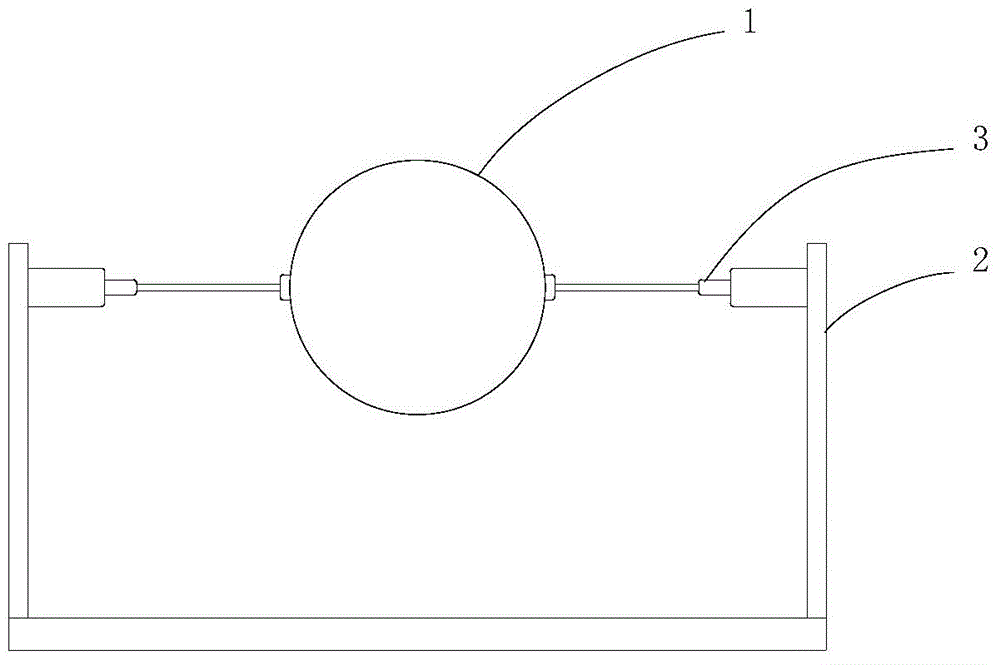
[0039] like figure 1 and figure 2 As shown, a flexible solar cell assembly includes a flexible solar cell 1, a bracket 2, a driving device 3 and a control device 4, the driving device 3 is installed on the bracket 2, and the driving device 3 is connected to the flexible solar cell 1 for The flexible solar cell 1 is driven to deform according to the illumination angle, and the control device 4 is used to control the driving device 3 .
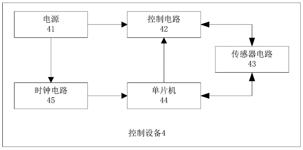
[0040] Wherein, the control device 4 includes a power supply 41, a control circuit 42, a sensor circuit 43, a single-chip microcomputer 44 and a clock circuit 45, and the power supply 41 supplies power for the control device 4 as a whole. , the control circuit 42 , and the sensor circuit 43 are respectively connected, and the sensor circuit 43 is connected to the control circuit 42 , and the control circuit 42 is connected to the driving device 3 to provide a driving signal for the driving device 3 . And in this embodiment, the driving device...
Embodiment 2
[0043] like figure 2 and image 3 As shown, a flexible solar cell assembly includes a flexible solar cell 1, a bracket 2, a driving device 3 and a control device 4, the driving device 3 is installed on the bracket 2, and the driving device 3 is connected to the flexible solar cell 1 for The flexible solar cell 1 is driven to deform according to the illumination angle, and the control device 4 is used to control the driving device 3 .
[0044] Wherein, the control device 4 includes a power supply 41, a control circuit 42, a sensor circuit 43, a single-chip microcomputer 44 and a clock circuit 45, and the power supply 41 supplies power for the control device 4 as a whole. , the control circuit 42 , and the sensor circuit 43 are respectively connected, and the sensor circuit 43 is connected to the control circuit 42 , and the control circuit 42 is connected to the driving device 3 to provide a driving signal for the driving device 3 . The driving device 3 is a linear motion dr...
Embodiment 3
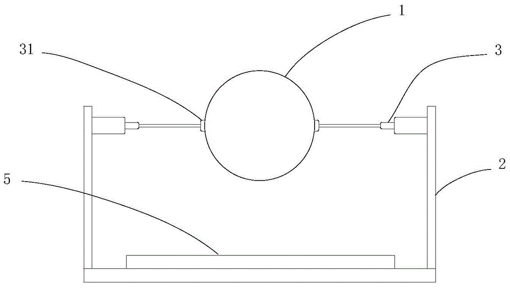
[0049] like figure 2 and Figure 4 As shown, a flexible solar cell assembly includes a flexible solar cell 1, a bracket 2, a driving device 3 and a control device 4, the driving device 3 is installed on the bracket 2, and the driving device 3 is connected to the flexible solar cell 1 for The flexible solar cell 1 is driven to deform according to the illumination angle, and the control device 4 is used to control the driving device 3 .
[0050] Wherein, the control device 4 includes a power supply 41, a control circuit 42, a sensor circuit 43, a single-chip microcomputer 44, and a clock circuit 45. The power supply 41 supplies power for the control device 4 as a whole. The power supply 41 is connected to the flexible solar cell 1, and the flexible solar cell 1 generates The electric energy provided to the power supply 41, the single-chip microcomputer 44 is connected with the clock circuit 45, the control circuit 42, the sensor circuit 43 respectively, and the sensor circuit ...
PUM
 Abstract
Description
Claims
Application Information