

A super-stabilization treatment method for in-situ crystallization catalyst with high rare earth content
A technology with high rare earth content and in-situ crystallization, applied in physical/chemical process catalysts, molecular sieve catalysts, chemical instruments and methods, etc.
- Summary
- Abstract
- Description
- Claims
- Application Information
AI Technical Summary
Problems solved by technology
Method used
Image

Examples
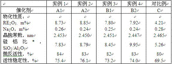
example 1
[0034] (1) Ammonium exchange
[0035]Add 1200g of deionized water to the stainless steel kettle, add 300g of in-situ crystallization NaY catalyst and 90g of ammonium chloride under stirring conditions, adjust the pH value to 3.0-4.0 with 4% dilute hydrochloric acid solution, and exchange at 80°C for 40 minutes , filtered, and the filter cake was rinsed with deionized water, and exchanged again in the same way to obtain Na 2 NH with O content below 4.0m% 4 Y-type catalyst.
[0036] (2) Rare earth exchange
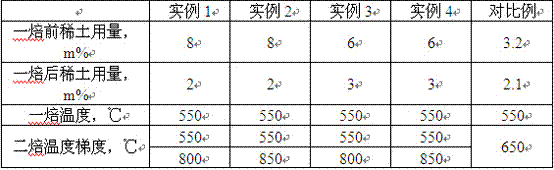
[0037] Add 1200g of deionized water to the above product, add RECl 3 Rare earth (RE 2 o 3 8% of the weight of the catalyst) solution, at a pH of 3.0-4.0, exchanged for 40 minutes at 80°C to obtain REY and NH 4 Type Y catalyst mixture.
[0038] (3) Once roasted
[0039] The above mixture was hydrothermally calcined at 550° C. for 4 hours.
[0040] (4) Rare earth supplementation for materials after first roasting
[0041] Add 1200g of deionized water and 60g of ammon...
example 2
[0047] According to the method of Example 1, the in-situ crystallized NaY type product is subjected to ultra-stabilization modification treatment: wherein the step (5) roasting temperature gradient is: the filter cake is roasted at 550°C for 2 hours, and then heated to 850°C and then roasted for 2 hours. Other conditions are the same as example 1 to obtain catalyst A2.
example 3
[0049] (1) Ammonium exchange
[0050] Add 1200g of deionized water to the stainless steel kettle, add 300g of in-situ crystallization NaY catalyst and 90g of ammonium chloride under stirring conditions, adjust the pH value to 3.0-4.0 with 4% dilute hydrochloric acid solution, and exchange at 80°C for 40 minutes , filtered, and the filter cake was rinsed with deionized water, and exchanged again in the same way to obtain Na 2 NH with O content below 4.0m% 4 Y-type catalyst.
[0051] (2) Rare earth exchange
[0052] Add 1200g of deionized water to the above product, add RECl 3 Rare earth (RE 2 o 3 6% by weight of the catalyst) solution, exchanged for 40 minutes at pH 3.0-4.0, 80°C, to obtain REY type and NH 4 Type Y catalyst mixture.
[0053] (3) Once roasted
[0054] The above mixture was fired at 550°C for 4 hours.
[0055] (4) After the first baking, the material is supplemented with rare earth
[0056] Add 1200g of deionized water and 60g of ammonium chloride to th...
PUM
 Abstract
Description
Claims
Application Information