Synchronous double-valve electromagnetic control oil atomizer

An electromagnetic control and fuel injector technology, which is applied in the direction of machines/engines, fuel injection devices, engine components, etc., can solve the problem of reducing valve flow, slowing the seating speed of the needle valve of the fuel injector, and reducing the sealing performance of the pilot ball valve, etc. The problem, achieve the effect of increasing rising speed and attenuation, ensuring fast response characteristics, and accelerating response speed

Active Publication Date: 2015-09-23
HARBIN ENG UNIV
View PDF5 Cites 6 Cited by
  • Summary
  • Abstract
  • Description
  • Claims
  • Application Information

AI Technical Summary

Problems solved by technology

Among them, the common rail fuel injection system is the fastest-growing and hottest electronically controlled fuel injection system at present, and the electronically controlled fuel injector is the key component of the common rail fuel injection system, which often uses the form of electromagnetic pilot ball valve to realize the control of fuel injection. However, there are still the following disadvantages: With the increase of the rail pressure, the hydraulic force acting on the pilot ball valve increases, making its closing speed slower, and the injector needle valve seating speed slower. The oil cut-off is not straightforward in the late stage of fuel injection, resulting in poor fuel atomization, deterioration of combustion in the diesel engine cylinder, and at the same time, the sealing performance of the pilot ball valve is reduced. If the preload of the return spring of the armature is increased to improve the closing speed and sealing performance of the pilot ball valve, For the conventional electromagnetic control valve, the opening speed of the valve will be slowed down. If the method of reducing the lift is further adopted to increase the electromagnetic force to meet the opening speed of the pilot ball valve, the flow area of ​​the valve will be reduced and the valve will be reduced. The flow rate of the small valve reduces the response speed of the needle valve, which is not conducive to the multiple injection of the fuel injector. The response speed of the fuel injector under the full working condition of the diesel engine must be improved

Method used


Image

  • Synchronous double-valve electromagnetic control oil atomizer
  • Synchronous double-valve electromagnetic control oil atomizer
  • Synchronous double-valve electromagnetic control oil atomizer

Examples


Embodiment Construction

[0034] The present invention is described in more detail below in conjunction with accompanying drawing example:

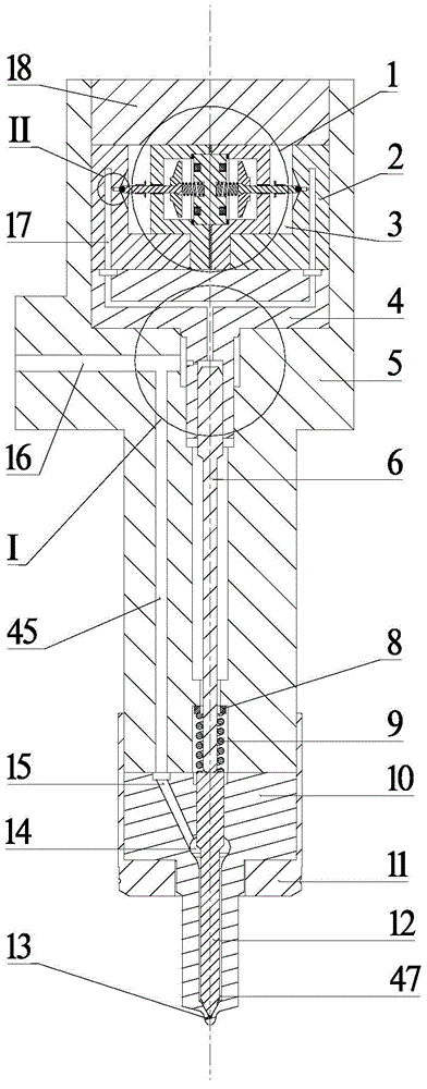
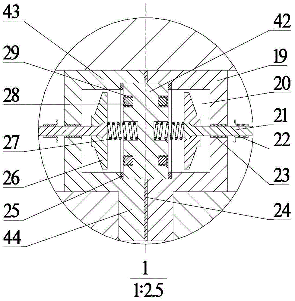
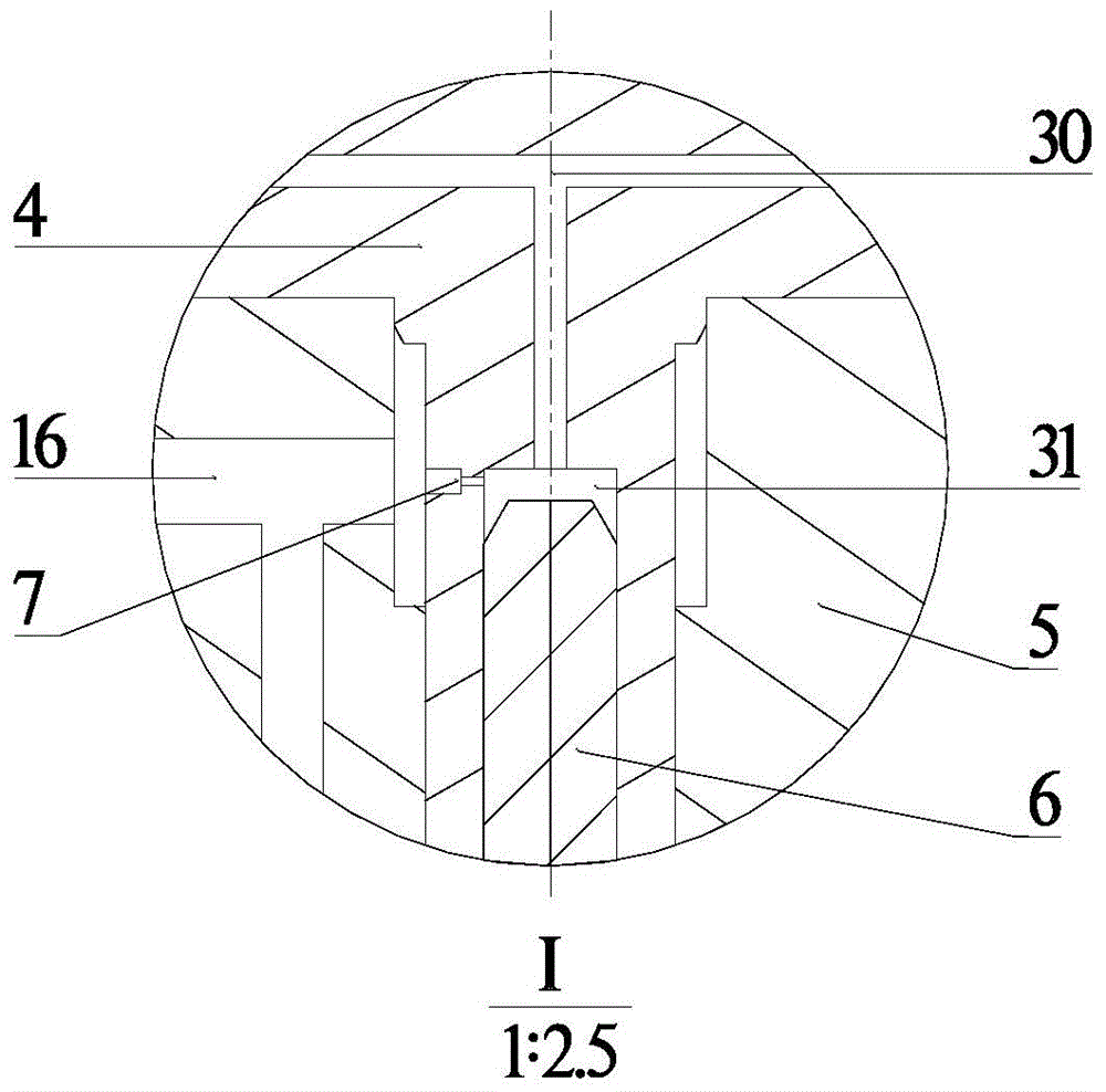
[0035] combine Figure 1~14. The composition of the first embodiment of the synchronous dual-valve electromagnetic control injector of the present invention includes a synchronous dual-valve electromagnet assembly 1, pilot ball valve seat 2, steel ball 32, control piston body 4, injector body 5, Needle valve ejector rod 6, needle valve return spring seat 8, needle valve return spring 9, nozzle 10, nozzle fastening nut 11, needle valve 12 and injector head fastening nut 18. The needle valve ejector rod 6 and the control piston body 4 are sequentially installed from the upper part of the injector body 5, and the two pilot ball valve seats 2, two steel balls 32 are symmetrically matched with the synchronous double valve electromagnet assembly 1 and placed on the upper part of the control piston body 4, The injector head is fixed by the fastening nut 18, the needle v...


PUM


Abstract

The invention aims at providing a synchronous double-valve electromagnetic control oil atomizer. The synchronous double-valve electromagnetic control oil atomizer comprises a synchronous double-valve electromagnet assembly, a pilot ball valve base, a steel ball, a control piston body, an oil atomizer body, a needle valve ejector rod, a needle valve reset spring base, a needle valve reset spring, a nozzle, a nozzle fastening nut, a needle valve and an oil atomizer head fastening nut. The synchronous double-valve electromagnet assembly structure is adopted, two pilot ball valves can be rapidly and synchronously controlled, the requirement for ball valve control flow and response can be met, the effect of the rail pressure change on the movement of the ball valves can be reduced, and the rapid response characteristic of the diesel engine total-working-condition oil atomizer is guaranteed. In addition, the structure of an axial cooling type iron core and a radial coil is adopted in the synchronous double-valve electromagnet assembly, the heat dissipation area of the coil and the iron core is increased, the interior of the iron core and the coil are well cooled, and good electric conduction performance, safety and reliability of the coil and good magnetic conduction performance of iron core materials are guaranteed.

Description

technical field [0001] The invention relates to an injection device, specifically a diesel fuel injector. Background technique [0002] Since the beginning of the 21st century, diesel engines have faced the challenges of energy and environmental constraints. Improving economy and controlling emissions have become important issues facing the diesel engine industry today. Electronically controlled fuel injection systems have high injection pressure and injection timing. It is an effective means to improve the high fuel economy of diesel engines and reduce harmful emissions, and has been widely used. Among them, the common rail fuel injection system is the fastest-growing and hottest electronically controlled fuel injection system at present, and the electronically controlled fuel injector is the key component of the common rail fuel injection system, which often uses the form of electromagnetic pilot ball valve to realize the control of fuel injection. However, there are stil...

Claims


Application Information

Patent Timeline
Patent Type & Authority Applications(China)
IPC IPC(8): F02M51/06F02M61/10F02M61/16F02M61/18
Inventor 范立云刘鹏马修真赵建辉许德宋恩哲董全
Owner HARBIN ENG UNIV
Why Eureka
Try Eureka