Method and for purifying exhaust gas

A technology of exhaust gas and catalyst, applied in the field of devices implementing the method

Inactive Publication Date: 2015-09-23
化学热处理技术有限责任公司
View PDF1 Cites 2 Cited by
  • Summary
  • Abstract
  • Description
  • Claims
  • Application Information

AI Technical Summary

Problems solved by technology

[0006] A further major disadvantage is that, in the known process with three regenerators, if a uniformly extruded material or corrugated SCR catalyst made of relatively soft material is to be used instead of the significantly more expensive coated SCR-catalytically active For washcoat ceramic honeycomb heat exchangers, at least three grids per regenerator are necessary for structural reasons

Method used


Image

  • Method and for purifying exhaust gas
  • Method and for purifying exhaust gas
  • Method and for purifying exhaust gas

Examples


Embodiment Construction

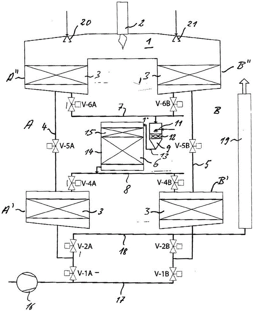
[0074] according to figure 1 , the regenerative thermal afterburner has two regenerators A and B connected by means of a common combustion chamber 1 to a burner 2 or an electric heating. In the combustion chamber 1 in which the temperature is eg 900° C., the exhaust gas is thermally purified.

[0075]Regenerators A and B are each divided into two in the flow direction. That is to say they each consist of a lower section A' and B' facing away from the combustion chamber 1 and an upper section A'' and B'' facing the combustion chamber 1 respectively. Sections A', A'', B' and B'' are each filled with heat accumulators 3.

[0076] The two sections A', A'' and B', B'' of each regenerator A and B are connected to each other by means of pipes 4 and 5 respectively, each provided with shut-off valves V-5A and V-5B.

[0077] The two regenerators A and B have a common SCR catalyst 6 .

[0078] For this purpose, the upper sections A'' and B'' are connected at their lower ends to the ...


PUM


Abstract

In order to purify exhaust gas containing nitrogen oxide combined with CO, VOC or nitrous oxide, especially exhaust gas generated during the production of cement clinker, nitric acid, adipic acid, fertilizer and uranium trioxide, a regeneration-type post-heat burning system equipped with at least two regenerators (A, B) is employed and the CO, VOC and nitrous oxide are purified thermally in a combustor (1) under the temperature from 800 DEG C to 1000 DEG C through the system. The thermal recovery of oxynitride is achieved through the adding of a hydronitrogen SCR catalyst (6), wherein the purified exhaust gas is removed out at a proper position from the corresponding two regenerators (A, B) under the temperature of about 300 DEG C. and is guided in a fixed flowing direction through the hydronitrogen SCR catalyst (6) and then fed back to the remaining sections (A', B') of the two regenerators (A, B).

Description

technical field [0001] The invention according to the preamble of claim 1 relates to a method. The invention also relates to a device for carrying out the method and to the use of the device. Background technique [0002] The combination of a regenerative thermal afterburning system with selective catalytic reduction (SCR) is known from DE19905733B4. In this method, SCR catalyst materials are each disposed on a regenerative heat exchanger material, thereby achieving thorough catalytic denitrification with high thermal efficiency when adding a reductant at the regenerator inlet. However, this method does not allow the simultaneous purification of organic components because the temperature above the catalyst is not sufficient to thermally oxidize organic contaminants. [0003] A method for purification of exhaust gases according to the preamble of claim 1 is known from EP472605B1, wherein the regenerator is divided vertically into three sections ( FIG. 4 ). First, the exhau...

Claims


Application Information

Patent Timeline
Patent Type & Authority Applications(China)
IPC IPC(8): F23G7/07B01D53/90B01D53/56B01D53/62B01D53/44B01D53/96
CPCB01D53/44B01D53/56B01D53/62B01D53/90B01D53/96F23G7/07Y02A50/20Y02C20/10Y02P20/30
Inventor 克里斯蒂安·穆勒德
Owner 化学热处理技术有限责任公司
Why Eureka
Try Eureka