
Laser dual-axis differential confocal induced breakdown-Raman spectroscopy imaging detection method and device

A dual-axis differential confocal and laser-induced breakdown technology, which is applied in Raman scattering, material excitation analysis, etc., can solve the problem of limiting the improvement of spectral detection resolution, restricting the signal-to-noise ratio of the system, and insufficient spatial resolution of spectral detection. Advanced problems, to achieve the effect of improving the detection signal-to-noise ratio and spectral resolution, reducing spectral detection noise, and avoiding system stray light

Active Publication Date: 2017-08-25
BEIJING INSTITUTE OF TECHNOLOGYGY
View PDF6 Cites 0 Cited by
  • Summary
  • Abstract
  • Description
  • Claims
  • Application Information

AI Technical Summary

Problems solved by technology

[0006] 1) Due to the use of parallel laser beams to irradiate and excite samples to generate plasma, there are still problems such as large laser excitation spots and low spatial resolution of spectral detection;
[0007] 2) Parameters such as chemical bonds and molecular structures in the molecule cannot be detected, and the result restricts the accurate and complete acquisition of sample material component information;
[0008] 3) The backscattered light interference cannot be effectively suppressed, which restricts the improvement of the signal-to-noise ratio of the system, and further limits the improvement of the spectral detection resolution;
[0009] 3) The obtained sample component information cannot be combined with the sample morphology information, and in-situ high-resolution acquisition of sample morphology-component comprehensive information cannot be realized
[0011] Laser-induced breakdown spectroscopy focuses the intense pulsed laser on the sample surface to ionize the sample, which can excite the sample to generate plasma. The atomic and small molecular element composition information of the sample can be obtained by detecting the spectrum radiated by the energy decay of the plasma, but it cannot Obtaining the chemical bond and molecular structure information of the sample molecule, how to completely obtain the elemental composition and molecular structure information of the sample molecule is of great significance for high-precision analysis of the composition of the sample

Method used


Image

  • Laser dual-axis differential confocal induced breakdown-Raman spectroscopy imaging detection method and device
  • Laser dual-axis differential confocal induced breakdown-Raman spectroscopy imaging detection method and device
  • Laser dual-axis differential confocal induced breakdown-Raman spectroscopy imaging detection method and device

Examples


Embodiment 1

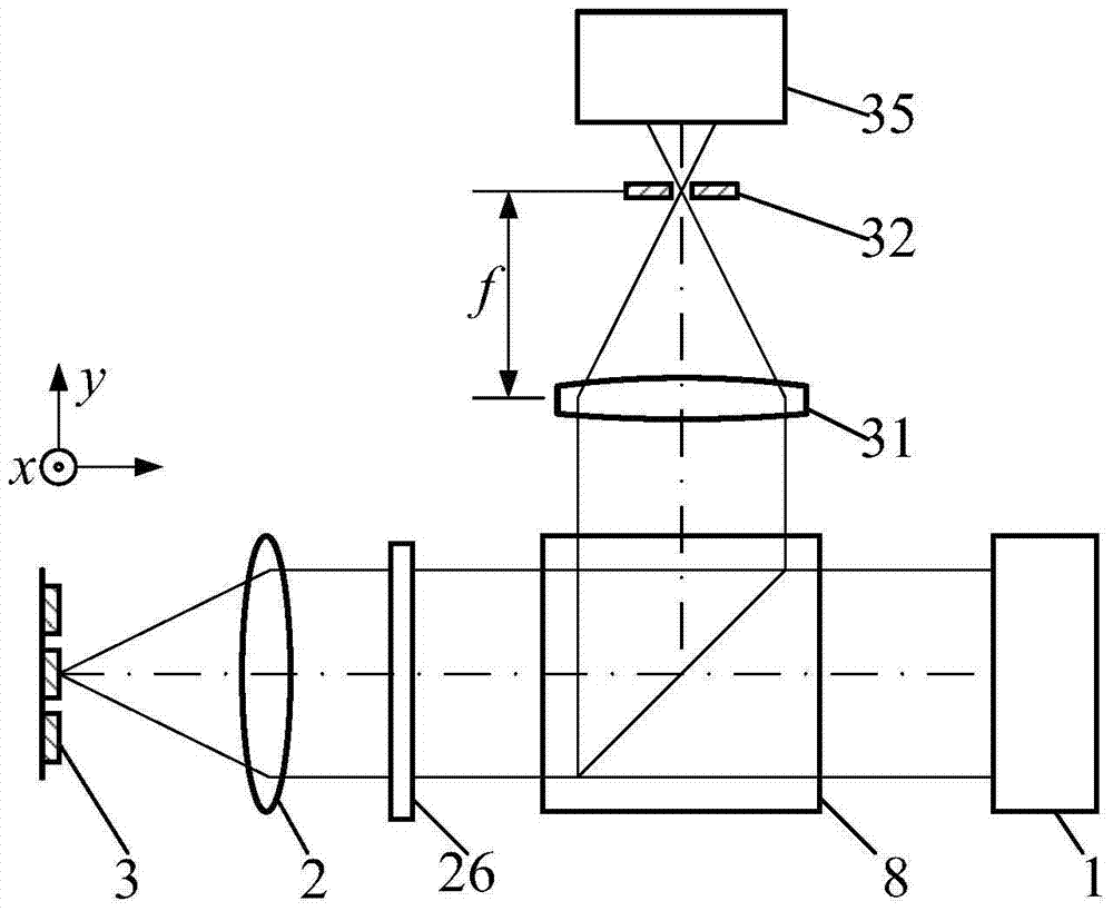
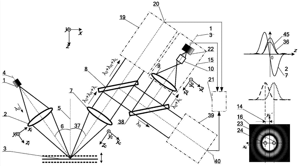
[0057] In this embodiment, the light source 1 is a laser, the polarization modulation device 29 is a radially polarized light generator, the dichroic light splitting system 38 is a Notch filter, the data processing system 21 is a computer, and the first detector 22 is a first CCD detector , the Raman spectrum detector 35 is a spectrum CCD detector.

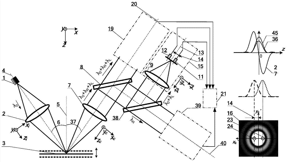
[0058] Such as image 3 , Figure 4 and Figure 7 As shown, the illumination objective lens 2 and the collection objective lens 7 are symmetrically distributed on both sides of the normal line 5 of the measurement surface, and the included angle between the illumination optical axis 4 and the normal line 5 of the measurement surface is θ 1 6. The angle between the collection optical axis 20 and the normal line 5 of the measurement surface is θ 2 37, where θ 1 = θ 2 , taking the 5 directions of the normal line of the measuring surface as the measuring axis, establishing a system coordinate system (x, y, z), a high spatial re...

Embodiment 2

[0076] In this embodiment, the polarization modulation system 29 is a radially polarized light generator, the dichroic light splitting system 38 is a Notch filter, the first detection system 11 is a first point detector, the second detection system 12 is a second point detector, data processing The system 21 is a computer, the first detector 22 is a first CCD detector, and the Raman spectrum detector 35 is a spectrum CCD detector.

[0077] Such as figure 2 , Figure 5 , Figure 6 and Figure 8 As shown, the embodiment 1 Figure 7 Replace the first CCD detector in the Figure 8 Two point detectors with the same parameters, namely the first point detector 11 and the second point detector 12, can constitute the second embodiment. The positions of the first point detector 11 and the second point detector 12 correspond to the positions of the first virtual pinhole 24 and the second virtual pinhole 23 in Embodiment 1, respectively. The positions of the first virtual pinhole 2...


PUM


Abstract

The invention belongs to the field of spectral measurement and imaging technology, and relates to a laser biaxial differential confocal induced breakdown spectrum-Raman spectrum imaging detection method and device, which can be used for high spatial resolution imaging of micro-region components and morphological parameters of samples. and detection. The method and device use laser-induced breakdown spectroscopy to detect elemental composition information of sample components; use Raman spectroscopy to detect chemical bond and molecular structure information of the sample; use biaxial differential confocal technology to detect sample surface morphology information, biaxial difference The dynamic structure has the advantages of large field of view and large working distance, which can accurately focus the sample, ensure the smallest illumination spot, and improve spectral excitation efficiency; the combination of the three can achieve structural sharing and functional complementation, and realize the morphology and composition of the sample Comprehensive measurement of information. The invention has the advantages of high spatial resolution, rich material component information and controllable measurement focus spot size, and has broad application prospects in the fields of minerals, metallurgy, space detection, environmental monitoring, biomedicine and other fields.

Description

technical field [0001] The invention belongs to the field of spectral measurement and imaging technology, and relates to a laser dual-axis differential confocal induced breakdown-Raman spectral imaging detection method and device. The differential confocal imaging technology is combined with the spectral detection technology to form a The high-resolution spectral imaging and detection method and device of "map-spectrum integration" can be used for multi-spectral comprehensive testing and high-resolution imaging of micro-region morphological components of samples. [0002] technical background [0003] Laser Induced Breakdown Spectroscopy (LIBS for short) is an in-situ detection technology for material components, which uses high-power-density lasers to excite the sample surface to generate laser-induced plasma. The atomic and ion spectral lines in the sample can be used to determine the composition of the sample. Its outstanding advantage is that it can detect the composition...

Claims


Application Information

Patent Timeline
Patent Type & Authority Patents(China)
IPC IPC(8): G01N21/65G01N21/63
CPCG01N21/718G01N21/65
Inventor 赵维谦王允邱丽荣
Owner BEIJING INSTITUTE OF TECHNOLOGYGY
Learn More