

Shield tunnel lifting hole wall penetration outward-extension type electromagnetic wave ground detecting system and application thereof
A shield tunnel, electromagnetic wave technology
- Summary
- Abstract
- Description
- Claims
- Application Information
AI Technical Summary
Problems solved by technology
Method used
Image

Examples
Embodiment Construction
[0036] The present invention will be further described below in conjunction with the embodiments shown in the accompanying drawings.
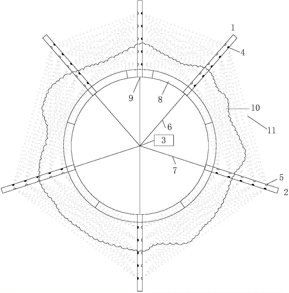
[0037] The shield tunnel hoisting hole breaks the wall and extends the electromagnetic wave ground detection system. The extended electromagnetic wave receiving probe rod 2 is assembled according to the detection range, and the transmitting source 4, the receiving source 5 and the transmission line are respectively embedded in it. The line interface of the electromagnetic wave emitting probe 1 and the extended electromagnetic wave receiving probe 2 is connected, and the extended electromagnetic wave emitting probe 1 and the extended electromagnetic wave receiving probe 2 can be placed on the shield through the hoisting hole 9 on the segment 8 In the boreholes around the tunnel, the electromagnetic wave 11 emitted by the transmitting source 4 scans the grouting body 10 and is received by the receiving source 5 .
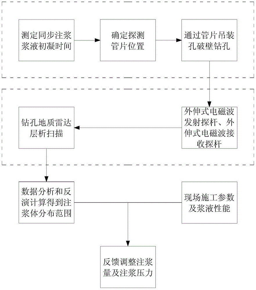
[0038] The specific steps are ...
PUM
| Property | Measurement | Unit |
|---|---|---|
| Diameter | aaaaa | aaaaa |
Abstract
Description
Claims
Application Information