
Electric energy and signal synchronous transmission method based on frequency splitting in electric energy wireless transmission

A technology of wireless transmission and frequency splitting, applied to electrical components, electromagnetic wave systems, etc., can solve problems such as system voltage gain drop

Inactive Publication Date: 2015-09-23
CENT SOUTH UNIV
View PDF2 Cites 14 Cited by
  • Summary
  • Abstract
  • Description
  • Claims
  • Application Information

AI Technical Summary

Problems solved by technology

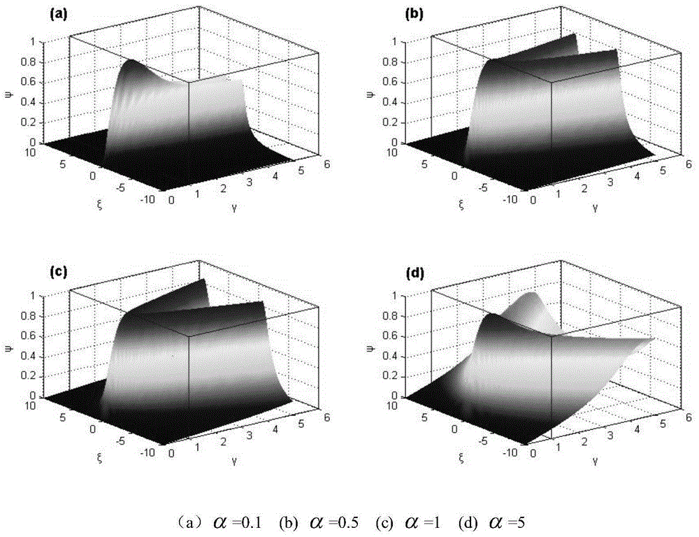
[0029] (1) At γ=1 (critical coupling), when the system works at the resonance point, the system voltage gain is the maximum; at γ>1 (over-coupling), there is a frequency splitting phenomenon, but no matter at which resonance frequency point, the voltage The gain can achieve a maximum value; at γ<1 (under-coupling), with the decrease of the generalized coupling factor, the system voltage gain drops sharply
[0030] (2) Where γ>1 (over-coupling), there is a frequency splitting phenomenon, but no matter at which resonant frequency point, the voltage gain can achieve a maximum value, which is the condition that must be met to transmit signals using the frequency splitting phenomenon

Method used


Image

  • Electric energy and signal synchronous transmission method based on frequency splitting in electric energy wireless transmission
  • Electric energy and signal synchronous transmission method based on frequency splitting in electric energy wireless transmission
  • Electric energy and signal synchronous transmission method based on frequency splitting in electric energy wireless transmission

Examples


Embodiment Construction

[0074] The present invention will be described in further detail below in conjunction with the accompanying drawings.

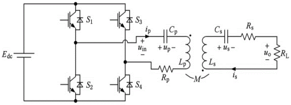
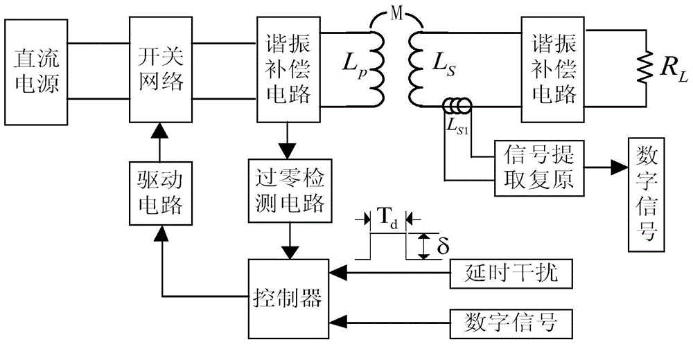
[0075] combined with figure 1 To attach Figure 5 , a method for synchronous transmission of electric energy and signals based on frequency splitting in wireless electric energy transmission, comprising the following steps,

[0076] The first step is to construct the following transmission system. The system includes a primary side resonant circuit and a secondary side resonant circuit; the primary side resonant circuit includes a DC power supply, a switch network, a primary side resonant compensation circuit, a transmitting coil, and a zero-crossing detection circuit. circuit, controller, drive circuit, delay interference module and digital signal input module; the secondary side resonant circuit includes receiving coil, secondary side resonant compensation circuit, load, coupling coil, signal extraction and recovery module and digital signal output module;...


PUM


Abstract

The present invention discloses an electric energy and signal synchronous transmission method based on frequency splitting in an ICPT (Inductively Coupled Power Transfer) system, in the method, a transmission system with a primary side resonance circuit and a secondary side resonance circuit is adopted, a controller in the system selects a time-delay interference parameter according to a digital signal, and forms an output control signal on the reference of a primary side resonance current zero-crossing detection signal for outputting to a drive circuit module, thereby finally achieving the purpose that the system switches between two autonomous stable resonant frequencies according to the digital signal to achieve signal frequency modulation and transmission; in addition, the secondary side resonance circuit is additionally provided with a coupling coil and a signal extraction and recovery module, which can achieve the process of coupling and picking a signal from the secondary side resonance circuit and performing recovery through the signal extraction and recovery module to obtain the digital signal. The electric energy and signal synchronous transmission method of the present invention facilitates high-efficiency transmission of electric energy in the ICPT system while achieving reliable transmission of signals in the case of not changing a topological structure of a main circuit of the ICPT system.

Description

technical field [0001] The invention relates to an inductively coupled power and signal synchronous transmission method, in particular to a frequency split-based power and signal synchronous transmission method in power wireless transmission. Background technique [0002] 1. Introduction to inductive coupling power transmission technology and signal transmission requirements [0003] Inductively coupled power transfer (hereinafter referred to as ICPT) technology is a new power transmission technology that uses high-frequency electromagnetic fields as the power carrier to wirelessly transmit power from the power supply to the load in the form of magnetic energy. The technology has the advantages of safety, reliability and flexibility. Inductively coupled power transfer technology has broad application prospects in the fields of rail transit, electric vehicles, consumer electronics, and biomedicine, and has become one of the research hotspots in the field of electrical engine...

Claims


Application Information

Patent Timeline
IPC IPC(8): H02J17/00
CPCH02J5/005
Inventor 谭建平刘溯奇薛少华吴志鹏
Owner CENT SOUTH UNIV
Learn More