DC-DC power supply device

A DC-DC, DC power supply technology, applied in high-efficiency power electronic conversion, conversion equipment with intermediate conversion to AC, climate sustainability, etc. Reduce the volume and weight of the device to achieve the effect of increasing the switching frequency, ensuring the safe operation of the system, and reducing costs

Inactive Publication Date: 2015-09-23
O&C ELECTRIC TECHN CO LTD
View PDF6 Cites 2 Cited by
  • Summary
  • Abstract
  • Description
  • Claims
  • Application Information

AI Technical Summary

Problems solved by technology

[0002] Traditional DC-DC conversion circuits usually use a single hard-switching chopper step-down circuit or a single isolated inverter circuit, which requires the use of high-voltage semiconductor devices to adapt to high input voltages, thus limiting the switching frequency of semiconductor components, resulting in circuit The electromagnetic components in it are bulky and costly, and do not have industrialization advantages
[0003] Our company applied for a patent on February 13, 2013, titled a three-level step-down circuit with interleaved work (application number: 201210501663. 2). The advantage of this circuit is that it adopts soft switching technology and can be used Semiconductor components of lower voltage level, and break through the restriction of power device safety switching time and diode turn-off loss on the switching frequency of step-down chopper circuit, so that the device can work at a higher operating frequency, thereby reducing the volume and weight of the device ; However, this circuit can only realize non-isolated voltage conversion on the one hand, thereby reducing the volume and weight of the device; however, this circuit can only realize non-isolated voltage conversion on the one hand, and requires electrical insulation in high input circuits and low output circuits. In some occasions, this topology cannot be realized; on the other hand, in applications where the input voltage is much higher than the output voltage, when the switching device of this circuit fails, it is easy to cause a series of failures in the output low-voltage circuit of the subsequent stage, and the reliability is not high.

Method used


Image

  • DC-DC power supply device
  • DC-DC power supply device
  • DC-DC power supply device

Examples


Embodiment 1

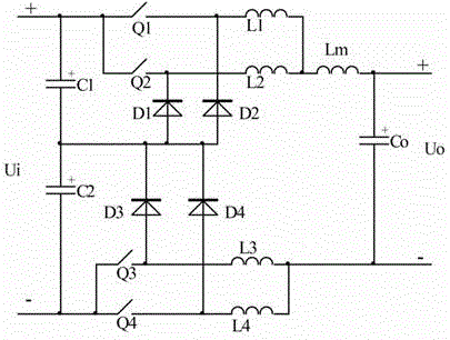
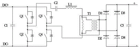
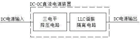
[0022] Such as image 3 Shown: a DC-DC direct current power supply device, including such as figure 1 The three-level step-down circuit shown and as figure 2 In the LLC resonant isolation circuit shown, the input terminal of the three-level step-down circuit is connected to the input DC power supply Ui, and the output terminal U0 of the three-level step-down circuit is connected to the DC input terminal of the DC power supply of the LLC resonant isolation circuit; the LLC resonant isolation circuit The output terminal of the DC power supply is connected to the DC power supply load, that is: the input DC power supply Ui is stepped down by a three-level step-down circuit to a lower DC voltage output, and then converted to a stable DC voltage output by an LLC resonant isolation circuit.

[0023] Such as figure 1 As shown: the three-level step-down circuit in this embodiment is composed of filter capacitors connected in sequence, a rectifier circuit composed of four diodes D1-D...


PUM


Abstract

The invention relates to a DC-DC power supply device. The DC-DC power supply device comprises a tri-level voltage reducing circuit and an isolating circuit, wherein the input end of the tri-level voltage reducing circuit is connected to an input power supply, and the output end of the tri-level voltage reducing circuit is connected to the input end of the isolating circuit; and the output end of the isolating circuit is connected with a load. By adopting the circuits provided by the invention, switch tubes with lower voltage classes can be used, and then the switching frequency of the switch tubes are improved to the maximum extent, the sizes and weights of transformers, inductors and the like are reduced, the cost is reduced, volume production is facilitated, and the system safety operation on a low output voltage side is guaranteed.

Description

technical field [0001] The invention relates to the technical field of power electronics, in particular to a DC-DC direct current power supply device. Background technique [0002] Traditional DC-DC conversion circuits usually use a single hard-switching chopper step-down circuit or a single isolated inverter circuit, which requires the use of high-voltage semiconductor devices to adapt to high input voltages, thus limiting the switching frequency of semiconductor components, resulting in circuit The electromagnetic components in the method are bulky and costly, and do not have industrialization advantages. [0003] Our company applied for a patent on February 13, 2013, titled a three-level step-down circuit with interleaved work (application number: 201210501663. 2). The advantage of this circuit is that it adopts soft switching technology and can be used Semiconductor components of lower voltage level, and break through the restriction of power device safety switching tim...

Claims


Application Information

Patent Timeline
Patent Type & Authority Applications(China)
IPC IPC(8): H02M3/28
CPCY02B70/10
Inventor 黄柱舒均庆王颖曜杨斌刘凡姚远蒙火成黄翔
Owner O&C ELECTRIC TECHN CO LTD
Why Eureka
Try Eureka