
Digital-analog combined gain temperature compensating circuit for travelling-wave tube amplifier

A technology of gain temperature compensation and combination of digital and analog, which is applied to gain control, amplifiers with propagation time effects, electrical components, etc., can solve problems such as insufficient temperature compensation margin, poor compensation matching, and large amount of debugging, so as to avoid The effect of high gain, improved stability, and reduced compensation range

Active Publication Date: 2015-09-23
XIAN INSTITUE OF SPACE RADIO TECH
View PDF10 Cites 7 Cited by
  • Summary
  • Abstract
  • Description
  • Claims
  • Application Information

AI Technical Summary

Problems solved by technology

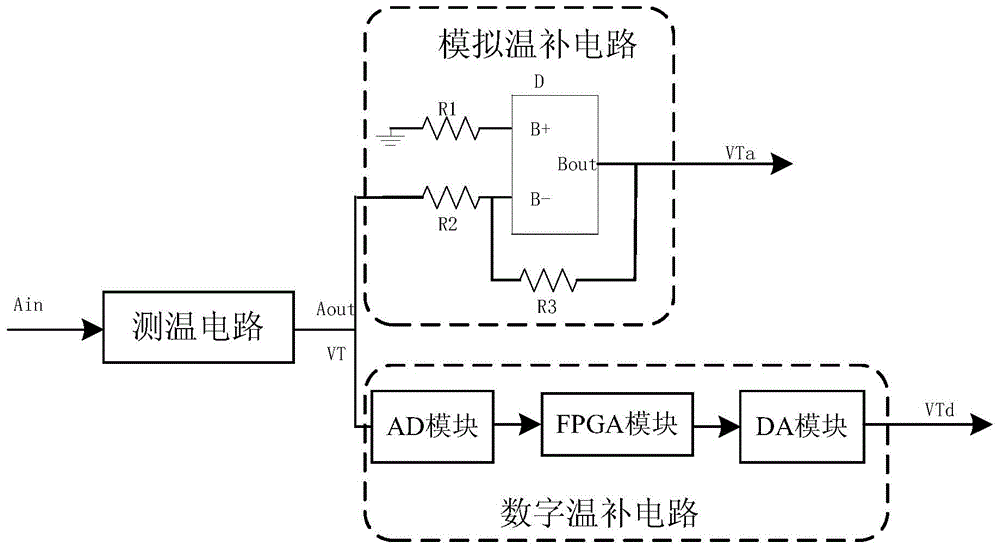
[0014] The purpose of the present invention is to overcome the deficiencies of the prior art, to provide a digital-analog combined line amplifier gain temperature compensation circuit, the circuit includes an analog temperature compensation circuit and a digital temperature compensation circuit, which can realize the temperature compensation of the combination of digital and analog, and can overcome Using analog temperature compensation or digital temperature compensation alone has disadvantages such as large amount of debugging, insufficient temperature compensation margin, poor compensation matching, and easy self-excitation. The circuit implementation method is simple and can meet the requirements of miniaturization and low power consumption of spaceborne products. High compensation accuracy and large margin

Method used


Image

  • Digital-analog combined gain temperature compensating circuit for travelling-wave tube amplifier
  • Digital-analog combined gain temperature compensating circuit for travelling-wave tube amplifier
  • Digital-analog combined gain temperature compensating circuit for travelling-wave tube amplifier

Examples


Embodiment Construction

[0038] Below in conjunction with accompanying drawing and specific embodiment the present invention is described in further detail:

[0039] Such as figure 1As shown in the schematic diagram of the temperature compensation circuit, the digital-analog combined line amplifier gain temperature compensation circuit of the present invention includes a temperature measurement circuit, an analog temperature compensation circuit and a digital temperature compensation circuit, wherein:

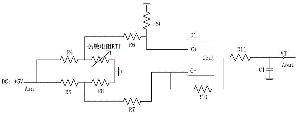
[0040] The input terminal Ain of the temperature measurement circuit receives the external input voltage V DC , the temperature measurement operation is performed to obtain the output voltage VT, and output to the analog temperature compensation circuit and the digital temperature compensation circuit through the output terminal Aout. In the present invention, the temperature measuring circuit can adopt a bridge temperature measuring circuit, such as figure 2 As shown, the circuit includes a thermis...


PUM

PropertyMeasurementUnit
Resistanceaaaaaaaaaa

Abstract

The invention provides a digital-analog combined gain temperature compensating circuit for a travelling-wave tube amplifier. The circuit comprises a temperature-measuring circuit, an analog temperature compensating circuit, and a digital temperature compensating circuit, digital-analog combined gain temperature compensation for the travelling-wave tube amplifier can be realized, wherein the analog temperature compensating circuit can realize coarse temperature compensation via the adjustment of an adjustable resistor, the digital temperature compensating circuit obtains a digital temperature compensating voltage corresponding to an output voltage of the temperature-measuring circuit via a set look up table (LUT) so that fine tuning of temperature compensation is realized, the defects that by individually employing analog temperature compensation or digital compensation, the debugging quantity is large, self excitation easily occurs within a temperature range, the margin of temperature compensation is not sufficient, and the compensation match is poor are overcome, the realization mode of the circuit is simple, the requirements of miniaturization and low power consumption of space-borne products can be met, the compensation precision is high, and the margin is wide.

Description

technical field [0001] The invention relates to the technical field of temperature compensation circuit design, in particular to a digital-analog combined traveling amplifier gain temperature compensation circuit, which can be applied to space-borne linearized traveling wave tube amplifier products. Background technique [0002] Linearized traveling-wave tube amplifiers are widely used in communication satellites and navigation satellites. The functions and performance of domestic linearized traveling-release products are compared with imported products, and they are used to replace imported products in various satellite projects. The consumption has increased sharply. Usually, a satellite needs Dozens of domestically produced products are used. The application of line amplifier products needs to ensure the consistency of performance under different temperature conditions, so the gain temperature compensation method of line amplifier products is particularly important. [0...

Claims


Application Information

Patent Timeline
IPC IPC(8): H03G3/20H03F3/58
Inventor 贺彬熊洁左鹏周斌康瑞媛王勇
Owner XIAN INSTITUE OF SPACE RADIO TECH
Learn More