High-speed low voltage phase frequency detector circuit

A frequency and phase detector, high-speed and low-voltage technology, applied in the direction of electrical components, automatic power control, etc., can solve the problems of limiting the maximum working speed of the circuit, limiting the maximum working speed of the PFD, and increasing the static power consumption of the PFD, reaching the fourth state and frequency discrimination and phase discrimination range are optimized, and the dead zone is suppressed and the phase discrimination range is good.

Inactive Publication Date: 2015-09-23
SOUTHEAST UNIV
View PDF4 Cites 3 Cited by
  • Summary
  • Abstract
  • Description
  • Claims
  • Application Information

AI Technical Summary

Problems solved by technology

[0003] The traditional PFD has the following disadvantages: 1. The output signals UP and DOWN of the PFD are used to control the charging and discharging switches of the subsequent charge pump respectively, so as to convert the frequency or phase difference into the VCO control voltage.
Due to the delay of the AND gate, the output signals UP and DOWN (that is, the fourth state) appear at the same time within a short period of time, and the appearance of the fourth state will increase the static power consumption of the PFD.
3. Due to the charging and discharging time of the gate of the MOS tube, the maximum operating speed of the circuit is limited, so the maximum operating speed of the traditional PFD is limited

Method used


Image

  • High-speed low voltage phase frequency detector circuit
  • High-speed low voltage phase frequency detector circuit
  • High-speed low voltage phase frequency detector circuit

Examples


Embodiment Construction

[0016] The present invention will be further explained below in conjunction with the accompanying drawings.

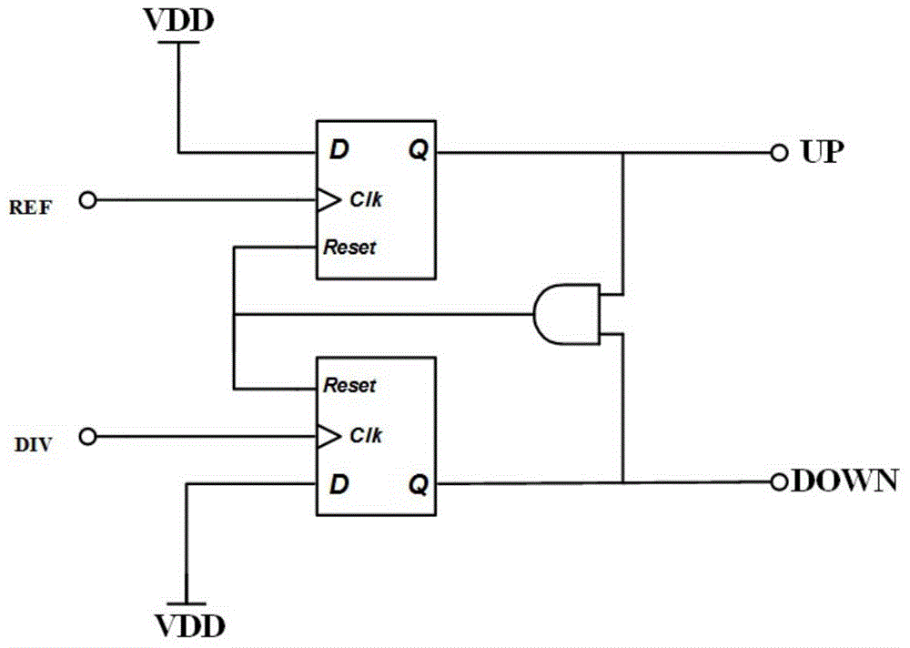
[0017] like figure 2 As shown, a high-speed low-voltage frequency and phase detector circuit includes a first pre-charge NSTSPC circuit, a second pre-charge NSTSPC circuit, a first delay circuit, a second delay circuit, a first reset circuit, and a second reset circuit . The reference signal REF is input to the signal input terminal of the first precharge NSTSPC circuit, the feedback signal DIV is input to the signal input terminal of the second precharge NSTSPC circuit, the first precharge NSTSPC circuit outputs an UP signal, and the second precharge NSTSPC circuit outputs a DOWN signal.

[0018] Wherein, the first delay circuit is used to delay the reference signal REF by τ0 time and input it to the first reset circuit. The first reset circuit is used to perform an AND logic operation on the reference signal REF and the reference signal REF delayed by τ0, and then...


PUM


Abstract

The invention relates to a high-speed low voltage phase frequency detector circuit, comprising a precharging NSTSPC circuit, a reset circuit, and a delay unit, namely, adopting a feedforward staggered form reset structure. Rising edge detection is performed on each input signal, after delay, NAND logical operation is performed on the input signal and an original input signal, OR logical operation is performed on the result and a corresponding output (UP or DOWN) phase, so as to cross and connect to a reset terminal of the NSTSPC circuit at the opposite edge to force the NSTSPC circuit at the opposite edge to reset. The precharging NSTSPC circuit is adopted for precharging feedforward staggered reset; under the condition of low working voltage and high phase demodulation frequency, the circuit can guarantee to well suppress a dead zone and a fourth state, and has a phase demodulation range close to between negative 2pi and positive 2pi and good linearity.

Description

technical field [0001] The invention belongs to an analog radio frequency integrated circuit, in particular to a novel high-speed low-voltage frequency and phase discrimination circuit for a phase-locked loop. Background technique [0002] The traditional PFD adopts D flip-flop, which is triggered by rising edge, as attached figure 1 shown. Compare the frequency or phase between the input signal reference signal REF and the feedback signal DIV, and output the frequency or phase difference of the two input signals in the form of digital quantities (UP and DOWN). f REF >f DIV , or f REF =f DIV But when the phase of REF is ahead of DIV, the output UP of PFD is a positive pulse, and the pulse width is related to the frequency difference or phase difference between the two input signals, while DOWN is always low. On the contrary, when f DIV >f REF , or f DIV =f REF But when the phase of DIV is ahead of REF, the output DOWN of PFD is a positive pulse, and the pulse...

Claims


Application Information

Patent Timeline
IPC IPC(8): H03L7/085
Inventor 韩婷婷田密徐建王志功
Owner SOUTHEAST UNIV
Why Eureka
Try Eureka