Swinging spinning and winding noodle extension machine

A stretching machine and swing-type technology, which is applied in the field of swing-type spinning and winding noodle stretching machines, can solve problems such as high labor intensity, impact on eating, and inability to cook, so as to reduce labor intensity of workers, improve work efficiency, and maintain product quality. quality effect

Active Publication Date: 2015-09-30
巴彦淖尔市冠生园食品有限责任公司
6 Cites 9 Cited by

AI-Extracted Technical Summary

Problems solved by technology

[0002] Along with the raising of economic level and the quickening of pace of life, instant edible, easy to store dried noodles have appeared on the market, and the dried noodles sold on the market are mostly extruded or pressed into sheets and directly cut into strips or flakes. Boiling resistance, easy to break after cooking, poor taste, and affect eating; while ramen is produced...

Abstract

The invention discloses a swinging spinning and winding noodle extension machine. The swinging spinning and winding noodle extension machine comprises a rack, a driving mechanism mounted on the rack, a horizontal reciprocating noodle conveying mechanism, a guiding frame and a swinging extension mechanism; the driving mechanism comprises a driving motor, a clutch and a speed reducer; the horizontal reciprocating noodle conveying mechanism comprises a reciprocating eccentric wheel, a reciprocating noodle conveying base and noodle conveying pipes; vertically arranged noodle feeding pipes are arranged at the bottom of one side of the guiding frame; a guiding pulley block is transversely arranged on the guiding frame above the feeding pipes; a noodle feeding pulley is axially and horizontally arranged on the other side of the guiding frame, and is in transmission connection with the output shaft of the speed reducer; the swinging extension mechanism comprises a swinging eccentric wheel, a displacement lead screw, a guiding rod, a swinging shaft, a swinging counter shaft, a swinging seat, a swinging head and noodle hanging rods. The swinging spinning and winding noodle extension machine has the advantages that mechanized and automatic noodle extension production can be realized, automatic production is realized, the labor is saved, the worker labor intensity is reduced, the working efficiency is improved, the drawn noodles are consistent in length, and uniform in thickness, and consistent product quality is maintained.

Application Domain

Dough shaping

Technology Topic

Image

  • Swinging spinning and winding noodle extension machine
  • Swinging spinning and winding noodle extension machine
  • Swinging spinning and winding noodle extension machine

Examples

  • Experimental program(1)

Example Embodiment

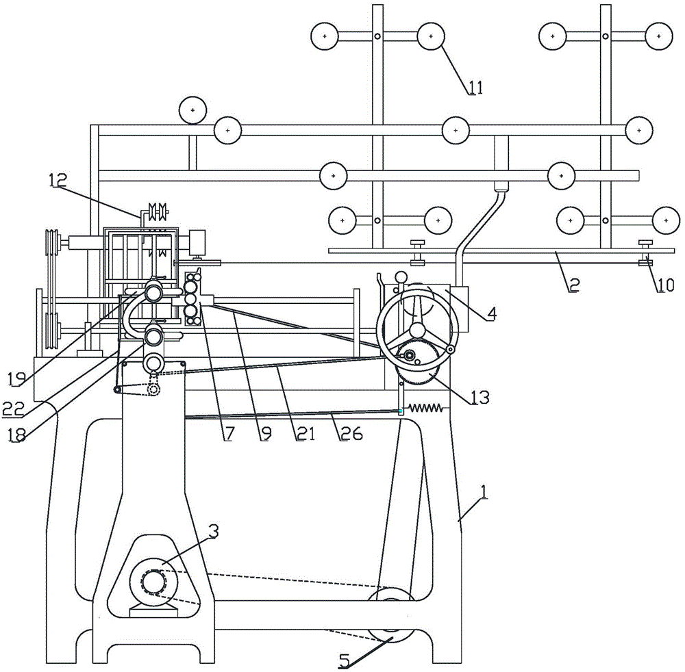
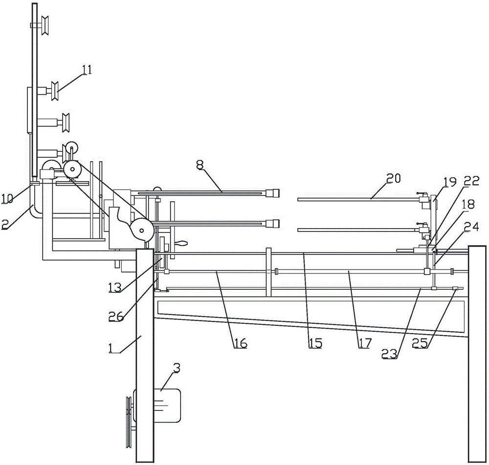
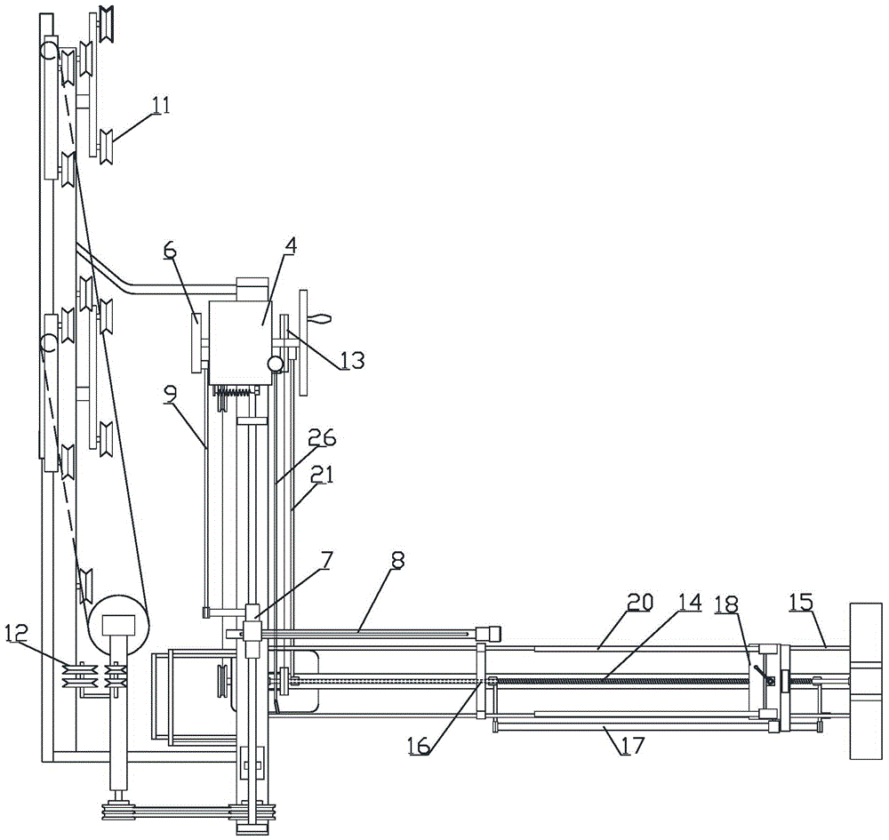
[0010] Such as Figure 1 to Figure 3 As shown, the swing type spinning noodle stretching machine includes a frame 1, a driving mechanism installed on the frame 1, a horizontal reciprocating noodle feeding mechanism, a guide frame 2, a swing stretching mechanism, and the driving mechanism includes a driving motor 3, Clutch 4, reducer 5, drive motor 3 and clutch 4 input shaft are connected by belt transmission, clutch 4 output shaft is connected with reducer 5 input shaft in transmission; horizontal reciprocating surface mechanism includes reciprocating eccentric 6, reciprocating surface base 7, The noodle feeding tube 8 is provided with a reciprocating eccentric 6 on the frame 1. The reciprocating eccentric 6 and the output shaft of the reducer 5 are connected by a belt drive; a horizontal reciprocating reciprocating noodle base 7 is slid on the frame 1, A reciprocating crank 9 is provided between the reciprocating eccentric 6 and the reciprocating surface base 7; the two ends of the reciprocating crank 9 are respectively articulated with the disk surface of the reciprocating eccentric 6 and the bottom 7 of the reciprocating surface, and the eccentric 6 passes The reciprocating crank 9 drives the reciprocating feeding surface base 7 to move back and forth; a hollow surface feeding tube 8 is horizontally provided on the reciprocating feeding surface base 7; a guide frame 2 is provided above the frame 1; a guide frame 2 is provided at the bottom of one side The upper tube 10 is vertically arranged, and the guide pulley block 11 is arranged horizontally on the guide frame 2 above the upper tube 10, and the distance between the pulleys of the guide pulley block 11 is adjustable; the other side of the guide frame 2 is provided with an axial horizontal The surface sending pulley 12 is provided; the surface sending pulley 12 is connected to the output shaft of the reducer 5; the swing stretching mechanism includes a swing eccentric 13, a displacement screw 14, a guide rod 15, a swing shaft 16, a swing secondary shaft 17, and a swing seat 18. The swing head 19, the noodle rod 20, the swing eccentric 13 and the reciprocating eccentric 6 are coaxially fixedly connected; the frame 1 is horizontally provided with a displacement screw 14 with the same axial direction as the noodle tube 8, which is A guide rod 15 is provided on the frame 1 on both sides of the screw 14 in parallel. The displacement screw 14 and the swing eccentric 13 are connected by belt transmission. The frame 1 under the displacement screw 14 is provided with an axial and displacement wire The rocking shaft 16 axially parallel to the bar 14 is fixed with a rocking secondary shaft 17 parallel to the rocking shaft 16; a crank rocking mechanism 21 is provided on the disk surface of the rocking eccentric 13 and the crank rocking mechanism 21 The top of the rocker arm is hinged with the rocking shaft 16; a rocking seat 18 is provided horizontally sliding on the two guide rods 15; the bottom of the rocking seat 18 is connected to the displacement screw 14 through a nut, and the displacement screw 14 can drive the rocking seat 18 while rotating Move along the precession direction of the displacement screw 14; a swing head 19 is provided for rotation on the swing seat 18, and two noodle rods 20 whose axial directions are parallel to the axis of the displacement screw 14 are movably inserted on the swing head 19; A rocking crankshaft 22 is provided between the rocking head 19 and the rocking secondary shaft 17; the two ends of the rocking crankshaft 22 are respectively articulated with the rocking head 19 and the rocking secondary shaft 17, and the rocking eccentric 13 is connected by a crank rocking mechanism 21, The rocking shaft 16, the rocking secondary shaft 17, and the rocking crankshaft 22 drive the rocking head 19 to swing up and down relative to the displacement screw 14; the frame 1 below the rocking seat 18 is provided with a clutch rod with the same axial direction as the displacement screw 14. 23. Clutch lever 2 3 One end is connected with the switch of the clutch 4 through the connecting rod 26; at the bottom of the swing seat 18 is provided a shift lever 24, the top of the shift lever 24 is slidably mounted on the clutch lever 23, and a stop 25 is provided on the clutch lever 23, the shift lever 24 The clutch 4 is closed by turning the stopper 25 to drive the clutch lever 23 and the connecting rod 26; the tangent to the top of the wheel surface of the surface sending pulley 12 and the lumen of the surface sending tube 8 are in the same horizontal plane; the axis of the surface sending tube 8 and the swing head The shaft axis of 19 is on the same horizontal plane.
[0011] Instructions for use: the top of the formed pre-processed noodles is inserted from the upper tube 10 first, hung on the guide pulley group 11, and then passed through the noodle conveying tube 8 through the noodle conveying pulley 12, and fixed on a noodle rod 20; drive motor 3 The swing base 18 is driven to move horizontally, and the swing head 19 on the swing base 18 swings horizontally and left and right. At the same time, the noodle feeding tube 8 is driven by the driving motor 3 to perform a horizontal and repeated displacement action, so that the noodles coming out of the noodle feeding tube 8 form an ∞ shape. Wound on the two noodle rods 20 on the swing head 19; by adjusting the distance between the pulleys on the guide pulley group 11, the noodles passing through the guide pulley group 11 can be stretched once; the noodles are wound around the swing head in an ∞ shape In the process of 19, the noodles are stretched twice.

PUM

no PUM

Description & Claims & Application Information

We can also present the details of the Description, Claims and Application information to help users get a comprehensive understanding of the technical details of the patent, such as background art, summary of invention, brief description of drawings, description of embodiments, and other original content. On the other hand, users can also determine the specific scope of protection of the technology through the list of claims; as well as understand the changes in the life cycle of the technology with the presentation of the patent timeline. Login to view more.

Similar technology patents

Multi-coin sorting and packing device

InactiveCN105976500AHigh precisionLabor savingCoin testingMagnet
Owner:SHANGHAI UNIV OF ENG SCI

Classification and recommendation of technical efficacy words

  • Labor saving
  • Reduce manual labor intensity

Pitaya high-quality and high-yield cultivation method adopting water and fertilizer integrated fertigation technology

InactiveCN104737743ALabor savingSolve labor difficultiesFertilising methodsHorticultureEchinocereus enneacanthusFrost
Owner:GUANGXI JIN HONG GUO AGRI COMPREHENSIVE DEV CO LTD
Why Eureka
Try Eureka