Electro-hydraulic synchronous bending machine and control method thereof

A bending machine and electro-hydraulic technology, applied in the direction of presses, manufacturing tools, etc., can solve the problems of high manufacturing cost and production cost, achieve the effect of reducing bending time, increasing lifting speed, and improving bending accuracy

Active Publication Date: 2015-09-30
SHAOXING ANYAXIN AUTOMATION TECH
View PDF8 Cites 8 Cited by
  • Summary
  • Abstract
  • Description
  • Claims
  • Application Information

AI Technical Summary

Problems solved by technology

[0003] The invention provides an electro-hydraulic synchronous bending machine and its control method, which solves the technical problem of high manufacturing cost and high production cost of the existing bending machine

Method used


Image

  • Electro-hydraulic synchronous bending machine and control method thereof
  • Electro-hydraulic synchronous bending machine and control method thereof
  • Electro-hydraulic synchronous bending machine and control method thereof

Examples


Embodiment 1

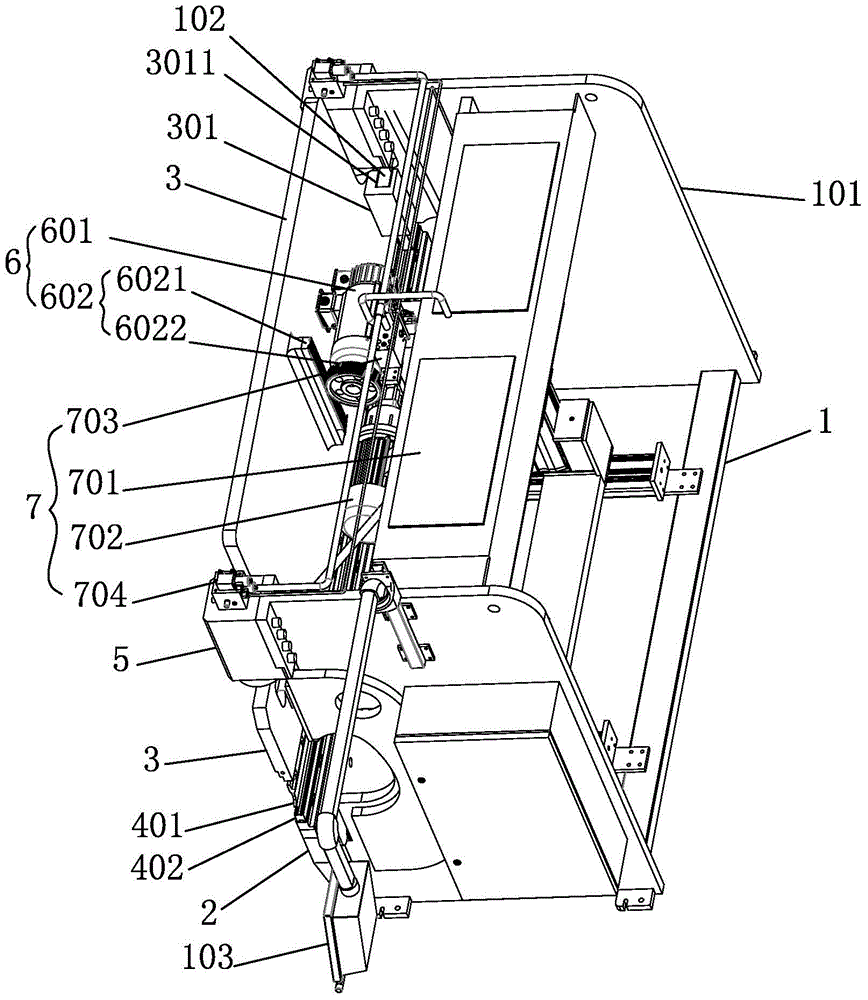
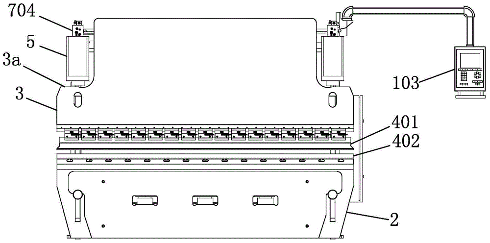
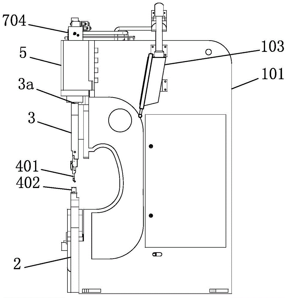
[0024] Embodiment 1: as Figure 1 to Figure 3 As shown, an electro-hydraulic synchronous bending machine includes a frame 1, a vertical plate 2 arranged on the frame 1, and a slider 3 arranged above the vertical plate 2. The lower end of the slider 3 is provided with an upper die 401, The upper end of vertical plate 2 is provided with lower mold 402, and the both sides of frame 1 is respectively provided with oil cylinder 5, and frame 1 comprises two side plates 101, and two oil cylinders 5 are fixed on the side plate 101 by bolt, two oil cylinders 5 The piston rods of the two cylinders are respectively connected to the slider 3, and the slider 3 is provided with two installation surfaces 3a, and the two installation surfaces 3a are located on the same horizontal plane, and the lower end surfaces of the piston rods of the two oil cylinders 5 are respectively connected to the two installation surfaces 301, The workpiece to be bent is placed on the lower mold 402, and the piston...

Embodiment 2

[0030] Embodiment 2: The difference from Embodiment 1 is that the transmission device 602 includes a lead screw and a screw nut, the lead screw is connected to the output shaft of the servo motor, and the screw nut is connected to the slider. The screw and nut form a ball screw structure, which has the advantages of high transmission efficiency and low noise.

[0031] A control method for an electro-hydraulic synchronous bending machine, including the following control stages:

[0032] 1) Standby stage: the bending machine is in the standby state after starting, the oil pump 702 is powered on, at this time the slider 3 is at the top dead center position, and the oil return port of the electromagnetic pressure valve 703 is opened;

[0033] 2) Fast-down stage: the control module issues a command to control the forward rotation of the servo motor 601, and the servo motor 601 drives the slider 3 to go down quickly through the transmission device 602 until the slider 3 reaches the ...


PUM


Abstract

The invention discloses an electro-hydraulic synchronous bending machine and a control method thereof. The technical problem that an existing bending machine is high in manufacturing cost and production cost is solved. The electro-hydraulic synchronous bending machine comprises a machine frame and a sliding block, oil cylinders are arranged on the two sides of the rack respectively, piston rods of the two oil cylinders are connected with the sliding block, and the bending machine further comprises an electric servo driving system, a hydraulic driving system and a control system. The electric servo driving system comprises a servo motor and a transmission device arranged on the servo motor and the sliding block, and the servo motor drives the sliding block to move vertically through the transmission device. The hydraulic driving system comprises oil tanks, an oil pump, an electromagnetic pressure valve and two proportional flow valves. An oil outlet of the oil pump is communicated with an oil inlet of the electromagnetic pressure valve, a pressure oil port of the electromagnetic pressure valve is communicated with oil inlets of the two proportional flow valves, and oil outlets of the two proportional flow valves are communicated with the two oil cylinders respectively.

Description

technical field [0001] The invention relates to an electro-hydraulic synchronous bending machine and a control method thereof. Background technique [0002] At present, the bending machine used for processing sheet metal parts is mainly driven by the oil cylinders on both sides of the slider to complete the entire bending process. Proportional reversing valves are respectively set on the oil circuits of the two oil cylinders to realize the lifting action of the slider. The proportional reversing valve is expensive, which increases the manufacturing cost of the bending machine. At the same time, due to the movement characteristics of the oil cylinder, the slider moves slowly, which makes it difficult to improve the production efficiency and increases the production cost. Contents of the invention [0003] The invention provides an electro-hydraulic synchronous bending machine and a control method thereof, which solve the technical problem of high manufacturing cost and high...

Claims


Application Information

Patent Timeline
IPC IPC(8): B21D5/00B30B15/16B30B15/22B30B15/14
CPCB21D5/004B30B15/161B30B15/166
Inventor 闫小军乌海东蔡朝晖其他发明人请求不公开姓名
Owner SHAOXING ANYAXIN AUTOMATION TECH
Why Eureka
Try Eureka